Interesting Tech Projects
Posts tagged software

Using Alibre Design for Multi-color and Multi-material 3D Printing Part II
Feb 27th
Previously I wrote about my little utility that allows exporting properly positioned STLs from Alibre Design so they can be imported into a slicing program for multi-color printing. This is fine for use with the RepRapPro slicer but perhaps not with other slicers.
Slic3r is a very popular, fast and flexible slicing program and now it also supports printing multi-color objects. The file format chosen by it’s author is AMF – Additive Manufacturing File. It is essentially a way to group STL files together into a single object and specify different colors or materials for various parts.
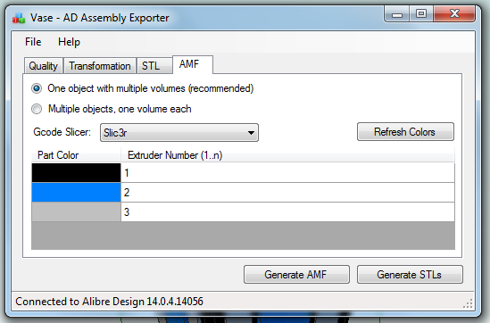
I’ve now updated my exporter utility to support saving Alibre Design assemblies directly to this format:
When an assembly is opened the application obtains the colors used by the parts in the assembly. It is then possible to assign the colors to extruders on the 3D printer. For example in this image black is the body of the object and has been assigned to the primary extruder. It’s necessary to choose which slicing program is being used as there isn’t a standard way of mapping colors to extruders. In particular Slic3r currently has several limitations so by choosing Slic3r the application will stop you from making invalid choices.
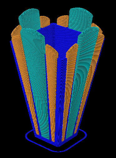
Once generated the AMF file can be loaded directly into Slic3r and sliced. Here is the g-code output shown in Repeiter-Host:
Note that the colors don’t match the Alibre Design assembly because Repetier-Host uses it’s own coloring scheme to represent the different extruders. For example blue is always the first extruder.
Now the object is ready to be printed. The estimated print time for this example is five hours and 45 minutes.

Ray Tracing (Rendering) with Alibre Design PE
Feb 15th
The Professional and Expert versions of Alibre Design come with a ray tracer called Keyshot but the Personal Edition of Alibre Design does not. However it is easily possible to use the free and very powerful Blender to generate ray traces of your 3D models.
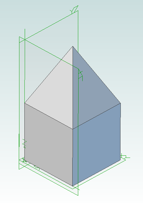
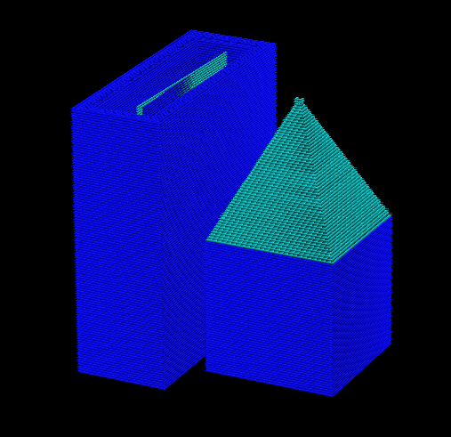
First you must design the parts in Alibre Design and put them together into an assembly. For example here is an assembly showing a pyramid stacked on top of a cube.
Now use my free utility AD Assembly Exporter to export the assembly as a set of STL files. You can download the utility from here. More details on using it can be found in my previous post on 3D printing with Alibre Design.
Next install and run Blender.
Press Delete to delete the default cube. Then go to File -> Import -> STL and choose the STL files that were generated. They will appear in the view in the same positions as they were in the assembly in Alibre Design.
Optionally you can select all the STLs and press ‘S’ to scale them down as they may be a bit large. Now you can assign materials, add lights, position the camera, etc. to render the scene.

Using Alibre Design for Multi-color and Multi-material 3D Printing
Feb 14th
When you wish to print out a part on a 3D printer the workflow is simple – design the part, export to STL and print it. This is fine when you are only printing with a single material or color. Becoming increasingly popular and affordable are 3D printers that support printing with two or three colors/materials at once, such as the Prusa Mendel from RepRapPro. How can Alibre Design be used for this scenario?
In general the easiest way to allocate different colors/materials to a part is to design that part using multiple smaller pieces. Each piece is assigned a color/material for printing. Alibre Design has a very flexible and easy to use way of grouping parts together called an assembly. What we would need therefore is a way of exporting multiple STLs from an assembly preserving their relationships to one another.
For example, suppose we have a cube and a pyramid and we wanted to place the pyramid on top of the cube and print it in a different color to the cube. We would design the cube and pyramid as two parts then use an assembly to stack the pyramid on top of the cube. Now we need to export the two STLs preserving their position relative to the same origin. This would allow the 3D slicing software to know to stack the pyramid on top of the cube. This is where the problems start.
Alibre Design supports exporting an assembly to a single STL. It merges all the parts together and produces a single object. Information about the individual parts is lost, so this is not usable for our purposes. If you export an individual part or you hide/suppress parts in an assembly then Alibre Design exports the STL using the position and origin in the part file not the assembly, causing the position information to be lost.
An additional problem is the units used in STL files are not defined. If you create a part using centimeters then Alibre Design exports an STL that uses centimeters. Likewise if you create a part using inches then the STL uses inches. The problem is that most, if not all, 3D slicing software assumes the units are millimeters. Solving this for a single part is easy – simply change the units used to millimeters before exporting. However an assembly can be made from multiple parts that all use different units. Regardless of the units chosen for the assembly the STL export will always use the units the part was designed with.
There is one more issue that needs to be addressed. When creating an assembly parts become rotated but the final positions may not be the best for 3D printing. Consider the lid for a box. When creating the assembly it will be rotated so the top is facing upwards but the optimal orientation for printing is probably for the top to be facing downwards onto the build surface. Currently the easiest way to rotate an assembly is to place it into a new assembly as a sub-assembly. This creates an unnecessary extra file and step to perform.
Fortunately Alibre Design has an easy to use API that allows these problems to be solved and I present here my free utility with an exciting name: AD Assembly Exporter.
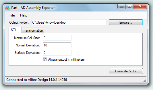
To use start the application and Alibre Design and open an assembly. In the assembly you can optionally hide/suppress parts you do not want to export. The name of the assembly will be shown in the title bar of the AD Assembly Exporter application. Enter the desired settings and click on the Generate STLs button.
The utility supports forcing the units in STLs to millimeters and rotation around an axis. The STL export options match those found in Alibre Design so please see the Alibre Design manual for a description of what they do. Sub-assembly nesting is supported.
Only open one assembly at a time when using the utility. It will export the first assembly found from your open Alibre Design sessions.
Please note that this software is provided “as-is”. More details can be found in the license shown during installation.
Click here to download AD Assembly Exporter (now called WizoPrint)
Radio Controlled Aircraft for Stroke Victims
Oct 23rd
This post introduces my open source radio control project. It allows an RC aircraft to be controlled from a Wii Nunchuk, i.e. with one hand! Videos will be posted when they are available but so far it is working great in the flight simulator and with a stationary aircraft.
All documentation, source files and binary files are available for free from this site, so you can build your own. Be sure to read the disclaimer before you start however.
I would love to hear your success stories using this modular system!
Part Design Tools and Workflow
Nov 19th
After spending quite some time trying different pieces of software I have come up with a collection and a workflow that I think will fit my needs.
I wanted to be able to accurately design parts in 3D, see how the parts will fit together to make sure they are right, and produce traditional engineering drawings of the parts, if possible. Also it is necessary once a part has been designed to be able to convert it into toolpaths, which is the path that a drill bit would move along to make the part. The toolpaths are represented using g-code which can be processed by EMC2 to move the stepper motors. Another requirement was to use free software where possible to try and keep costs down.
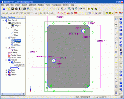
I start with Alibre Design Xpress. This is an excellent 3D design program that is also free. However free comes with a price, that is limitations. The key limitations are a limited number of export options and limited number of parts in an assembly. An assembly is a collection of parts fitted together to build something. However with enough perseverance these limitations can be overcome. In Design Xpress I created a simple test part that contains two holes for bolts:
Creating this 2D profile is very quick and easy. The holes are 0.174″ in diameter, which should be big enough for a #8 bolt. Next step is to extrude the 2D profile into a 3D part:
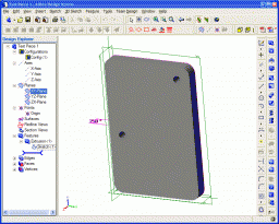
The part can be rotated and viewed from any angle. I decided to make the part 0.250″ thick. At this point Design Xpress can produce various numbers regarding the part, depending on the material it is made of. Choosing “Wood – southern pine” resulted in:
Volume = 1.480147117 in³
Mass = 1.576592260E-2 kg
Surface Area = 1.453202145E1 in²
Pretty interesting.
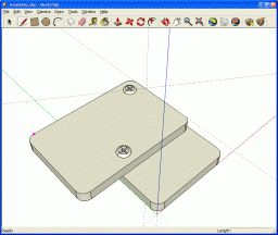
The software only allows five unique parts in an assembly, unless you register then it is 10. However this is quite a severe limitation in my opinion. Fortunately there is a way around this. Alibre has written an add-on called 3D Publisher for Google Sketchup that allows parts to be exported in Google’s Sketchup format. It’s not a requirement that the parts be uploaded to Google’s 3D Warehouse. Instead the exported parts can be saved to your hard drive. The following screenshot shows an assembly of two of the test parts along with size #8 bolts and nuts. The exact bolts are ANSI PHN, CRSHD TYPE II, B18.6.3, .164-36 UNF, 0.75, which gives an indication of the accuracy expected from designing parts and assembling them.
Again, this assembly can be rotated and the parts can be made transparent, along with plenty of other options. There is even a free add-on for Google Sketchup that provides a ray tracer. Assembling two parts confirmed my intention that the holes will line up.
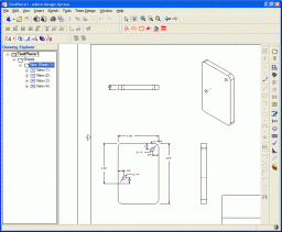
With a few mouse clicks Design Xpress can convert the 3D part into traditional engineering drawing:
This can be printed out, emailed, etc. and provides all the measurement details for someone else to reproduce the part without having access to electronic files. The drawing can also be exported as a DXF (without the annotations), which is needed for the next step.
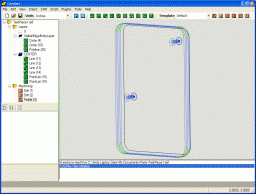
I found an excellent application to generate toolpaths for a part called CamBam. It takes a DXF file and provides an easy to use user interface in which you can select which items are profiled, drilled, pocketed, etc. Once the DXF file is loaded into CamBam all the unneeded views are deleted to leave the original 2D profile. For this part I added a 2.5D profile operation to cut the outline of the shape and two sprial drill operations for the holes:
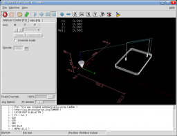
Cam Bam then generates the g-code which can be loaded in the AXIS interface in EMC2:
This process may seem convoluted, and it requires both Windows and Linux, but all the software can be obtained for free and is high quality. I haven’t completed my CNC machine yet, but I can watch the part being made in the AXIS interface without having the motors connected. I would expect that all the software will work in a Virtual Machine in Linux, however note that Design Xpress requires a lot of RAM to run (300Mb I believe).
Low Cost and Free CAD Programs
Nov 12th
I have stumbled across a large list of low cost and free CAD programs, mostly for Windows however. It seems there are many good choices in the list and I will try out a couple in the next day or two.
How To Install EMC2 on Unbuntu 7.10 Gutsy From Scratch
Nov 7th
April 2008 – Update – I’ve modified the instructions so that EMC2 can now be run as a user.
April 2008 – Update – Fixed some mistakes.
The following instructions will describe how to install the latest version of EMC2/LinuxCNC in Ubuntu 7.10 Gutsy Gibbon.
Why would you want to do this? You would do this if you don’t want to wait for new .deb files from the EMC2 team or you want to install EMC2 in the latest version of Ubuntu to take advantage of all the new features. The alternative is to use the Ubuntu 6.06 LTS live CD, install and then either stick with the software versions supplied or upgrade to the latest versions (such as device drivers, Gnome, Xorg, etc.), which is a big task itself.
Why would you not want to do this? I don’t recommend following these steps if you are unfamiliar with Linux and the shell/command prompt. It will either be a great learning experience or a very frustrating waste of time.
I am sure these steps can be simplified and improved, however they were created from many hours of experimenting and following dead-ends. I wanted to try and give you exactly what I ended up using, rather than an optimization. For example I’m sure that not all the reboots are needed, but they only take 60 seconds on my PC anyway.
These steps should work on a stock installation of Ubuntu 7.10, however I don’t make any claims that they will work for anyone else. If the software didn’t install correctly and the motors go crazy and move something that destroys your house, don’t blame me – these instructions are provided “as is” and without any warranty. Use at your own risk. If you spot a mistake please let me know and I will update the instructions.
Where you see “andy” replace with your own username, unless it is also “andy”. 🙂
‘$’ represents the prompt, to show you where the start of lines are. Don’t enter this, just what follows.
The process looks like this:
Get a vanilla kernel and patch it with RTAI support.
Test kernel.
Build and test RTAI modules.
Build EMC2.
Enable universe repository in /etc/apt/sources.list. Open a terminal window and then:
$ sudo apt-get update

$ sudo apt-get install build-essential libncurses5-dev kernel-package

$ cd /usr/src

$ sudo wget -c http://www.kernel.org/pub/linux/kernel/v2.6/linux-2.6.22.tar.gz

$ sudo tar xzvf linux-2.6.22.tar.gz

$ sudo mv linux-2.6.22 linux-vanilla-2.6.22

$ sudo ln -s linux-vanilla-2.6.22 linux

$ cd linux

$ sudo cp /boot/config-2.6.22-14-generic .config

$ sudo make menuconfig
At this point a menu will appear. Make the following choices:
Loadable module support > Module versioning support (N)
Loadable module support > Set version information on all module symbols (N)*
Processor type and features > Preemption model > Preemptible kernel (low latency desktop)
Processor type and features > Symmetric multi-processor support (N)**
Processor type and features > Local APIC support on uniprocessors (N)
Power management options (ACPI, APM) > ACPI support (N)
Power management options (ACPI, APM) > APM BIOS support (N)
Power management options (ACPI, APM) > CPU frequency scaling (N)
Kernel hacking > Compile the kernel with frame pointers (N)
* only if you have it in the menu
** only if your PC is not dual or quad core
Download rtai-3.6-test1.tar.bz2 from www.rtai.org (click on “RTAI Repository” link) to the desktop.
$ cd /home/andy/Desktop

$ bunzip2 rtai-3.6-test1.tar.bz2

$ tar xvf rtai-3.6-test1.tar
$ cd /usr/src/linux

$ sudo patch -p1 < /home/andy/Desktop/rtai-3.6-test1/base/arch/i386/patches/hal-linux-2.6.22-i386-1.10-09.patch
$ sudo make-kpkg --initrd --revision=1 --append-to-version=-realtime kernel_image kernel_headers
Some questions may appear which need to be answered (answer Y to any others that appear):
Interrupt pipeline – Y
Interrupt pipeline maintain backwards compatibility – Y
Interrupt pipeline debug – N
Now go and do something else for a while. On my P4 1.6GHz PC the kernel took 2 hours and 50 minutes to build.
$ cd ..

$ sudo dpkg -i linux-image-2.6.22-realtime_1_i386.deb

$ sudo nano -w /boot/grub/menu.lst
Find the line that looks like:
hiddenmenu
and change it to:
#hiddenmenu
If your PC already dual-boots (for example Ubuntu and Windows) then the hiddemenu is probably already commented out (using the ‘#’).
Save and exit nano.
Reboot and choose the realtime kernel from Grub menu.
Enter:
$ uname -a
and you should get something like:
Linux pepper 2.6.22-realtime #1 PREEMPT Sun Oct 28 10:54:43 MST 2007 i686 GNU/Linux
Make sure everything works ok (browsing, editing files, etc.)
Now we need to build the RTAI modules. This has to be done while running the realtime kernel we just built and booted into.
$ cd /home/andy/Desktop/rtai-3.6-test1

$ make menuconfig
Again a menu appears. Make the following selections:
Machine (x86) > Number of CPUs (enter the number you have here)
Exit and save configuration
$ make

$ sudo make install
Reboot back into the realtime kernel.
$ cd /usr/realtime/bin

$ sudo nano -w rtai-load
Change the first line from:
#!/bin/sh
to:
#!/bin/bash
and save. Then:
$ sudo nano -w /etc/init.d/create-rtai-devices.sh
Enter:
#!/bin/bash

mknod -m 666 /dev/rtai_shm c 10 254

for n in `seq 0 9`

do

f=/dev/rtf$n

mknod -m 666 $f c 150 $n

done
Save. Then:
$ sudo chmod 755 /etc/init.d/create-rtai-devices.sh

$ sudo update-rc.d create-rtai-devices.sh defaults
Reboot back into the realtime kernel.
Then test the RTAI support with:
$ cd /usr/realtime/testsuite/user/latency

$ sudo ./run

$ cd /usr/realtime/testsuite/user/preempt

$ sudo ./run

$ cd /usr/realtime/testsuite/user/switches

$ sudo ./run

$ cd /usr/realtime/testsuite/kern/latency

$ sudo ./run

$ cd /usr/realtime/testsuite/kern/preempt

$ sudo ./run

$ cd /usr/realtime/testsuite/kern/switches

$ sudo ./run
These tests spit out lots of numbers. The thing we are looking for here are kernel panics, system crashes, etc. Also make sure there are no overruns in the tests that display an overruns column.
If you get something like:
insmod: error inserting '/usr/realtime/modules/rtai_hal.ko': -1

Operation not permitted
then try:
$ sudo nano -w /boot/grub/menu.lst
and find the kernel line for the realtime kernel. Add “lapic” to the end of it and reboot, then run the tests again. For example:
kernel /boot/vmlinuz-2.6.22-realtime root=UUID=45d21232-cf0d-cc3d-87ce-8453214d7a6f ro quiet splash vga=794 lapic
Once you have the real time tests working continue with:
$ sudo nano -w /etc/modprobe.d/emc2
Enter:
install parport_pc /bin/true
Save then reboot back into the realtime kernel. Now to build and install EMC2.
$ sudo apt-get install python python-imaging python-imaging-tk python-numarray python-dev

$ sudo apt-get install tcl8.4-dev tk8.4-dev yapps2

$ sudo apt-get install libgtk2.0-dev libpth-dev libreadline5-dev libxmu-dev libxaw7-dev libglu1-mesa libglu1-mesa-dev libgl1-mesa-dev

$ sudo apt-get install pciutils-dev bwidget cvs latex2html preview-latex-style libaiksaurus-1.2-0c2a libgnomeprintui2.2-dev

$ sudo apt-get install imagemagick lyx
$ cd /usr/src

$ sudo dpkg -i linux-headers-2.6.22-realtime_1_i386.deb

$ cd ~

$ cvs -z5 -d:ext:anon@cvs.linuxcnc.org:/cvs co emc2

$ cd emc2/src

$ ./configure --with-realtime=/usr/realtime --with-kernel-headers=/usr/src/linux-headers-2.6.22-realtime

$ make

$ sudo make install
$ sudo nano -w /etc/security/limits.conf
Add the line:
* hard memlock 20480
Save and reboot into the realtime kernel.
To run EMC:
$ /usr/local/bin/emc
A window should appear with a choice of configurations. Choose Axis -> Sim and the Axis window should open. Congratulations EMC2 is now running!
Note that when running the realtime kernel the computer may not power itself off when the shutdown option is chosen. This is because the power management options have been disabled in the kernel. On my PC I wait a couple of minutes after the screen goes blank then press the power button on the front of the PC. This turns it off.
Windows XP and Stepper Motors
Nov 4th
My first test after assembling the board was to connect one motor to each axis in turn and test using Windows XP SP2 and Mach3. The test involved going to the motor tuning section and pressing the up and down arrows.
On the X and Y axis it was clear that steps were being lost. I had to turn the settings down to the lowest speed and even then there was the occasional loss of a step.
On the Z axis however the shaft only twitched. With identical settings to the X and Y axis it would not spin. So, the conclusion I drew was that there is a board problem with the Z axis.
Now I am testing with EMC2 running on Linux. My first test showed that all three axis, X, Y and Z appear to work just fine. The shaft spins quite happily on the Z axis…
So the moral of the story is that if one axis behaves differently it could be Windows causing it and not the board.
If you are stuck with Windows probably the only ways to determine where the problem lies are to either use a modified cable to swap pins around (so the problem axis is controlled by the pins for another axis) or to switch to TurboCNC and try that (perhaps with FreeDOS).
Testing EMC2/LinuxCNC on Ubuntu 7.10 Gutsy
Nov 3rd
I just completed the first test of running EMC2/LinuxCNC on Ubuntu with the HobbyCNC board. I connected a motor to the X-axis and started EMC2 with the “Axis” interface. I then told it to execute the default G-code file it loads with. Lo and behold the motor started spinning! I then moved the motor to the Y and Z axis and repeated. Seems to work well.
I didn’t notice any stalling so the problems I experienced with Windows XP and Mach3 must be due to Windows XP…
Here is a video:
Details on how to install EMC2 from source along with RTAI will follow when I have them ready. Also I will post the configuration files for the HobbyCNC board a bit further on in the project when I have more confidence that they are correct.
Updates
Oct 24th
I found out that the linux-rt kernel is not suitable for running EMC2/LinuxCNC. Sorry if you followed those steps. You can remove it using sudo apt-get remove linux-rt. Instead the kernel must be patched with RTAI. I’m currently working out the correct steps to do this. So far I tried the pre-built kernel in the Gutsy experimental folder but ethernet was broken. I don’t recommend bothering with those packages. Instead I hope to come up with the steps to install EMC2/LinuxCNC manually.
I have received most of the parts for the 24VDC, 10A power supply that is needed for the HobbyCNC board. Once I have that completed I will post a complete bill of materials with Digi-Key part numbers.
I damaged once of the stepper drivers on my HobbyCNC board while performing some simple tests with a bench power supply I have. The motor was connected incorrectly. Now I have to order a replacement. Luckily I was testing only one axis, otherwise I could have damaged all the drivers.
As you can see slow progress is being made on several fronts. Hopefully I will have something concrete to post soon.
