Interesting Tech Projects
Posts tagged robot
Jack the Ripper Bot V – Troubleshooting
Sep 7th
Part 1 introduced the project, part 2 covered the mechanics and part 3 the electronics. Part 4 covers the software side and part 5 is about troubleshooting.
1. Troubleshooting
- loosen the screws holding the servo and move it back slightly so the gears are still meshing but there is no sideways pressure on the servo shaft.
- make sure the pivot servo is not near the limit of it’s range at any point. When near the limit it will attempt continuous rotation and will lose it’s position.
- check the hub retainer is not touching the lower bearing.
- move the gear housing away from the servo and make sure it rotates freely.
- rotate the in tray outwards slightly and update the in tray position in config.xml. This will move the center of the in tray slightly further from the center of the pivot.
- make sure y axis is vertical (see item 6).
- rotate the out tray outwards slightly and update the out tray position in config.xml. This will move the center of the out tray slightly further from the center of the pivot.
- make sure y axis is vertical (see item 6).
- make sure both sides of the grabber are vertical.
- raise the toolhead microswitch so that more of the grabber is lowered into the hole in the center of the disc.
- make sure that the y axis is exactly horizontal.
- make sure that the y axis is exactly horizontal.
- check that the Y axis is vertical (see item 6).
- make sure that both sides of the grabber are vertical.
- make sure the hub retainer is close to, but not touching, the lower bearing.
- loosen the nuts holding the gear housing to the threaded rod and re-tighten while pressing down on the rear of the gear housing.
- check the y axis is securely attached to the threaded rod.
- adjust the two M8 nuts on the threaded rod at the hub to shorten/lengthen the arm from the pivot to y axis. Make sure the grabber is exactly over the center of the disc.
- tweak the drive tray position in config.xml
2. Ideas for Improvements
- Increase DVD capacity for faster PCs.
- Redesign main gear housing to use less plastic.
- Sugru veneers for grippers.
- Eliminate Raspberry Pi.
– merge BotServer into JacktheRipperBot.exe
– PC communicates directly with Pololu Maestro - PC farm for faster ripping
– use Raspberry Pi to create image of discs which are then put into a queue. A farm of PCs work on encoding the queue. - Cable management on top of support ring to keep wires away from gears.
- Stack two or three DVD drives vertically so the robot can load and unload into all of them.
- Add support for ripping “profiles” to JacktheRipperBot.exe, allowing different Handbrake settings to be used for specific discs in the in tray.
Jack the Ripper Bot IV – Software
Sep 6th
Part 1 introduced the project, part 2 covered the mechanics and part 3 the electronics. Part 4 covers the software side.
1. Maestro
Install the Pololu Maestro software and then connect the Maestro to your PC and start the software.
The microswitches should already be displaying their status. Press the switches and make sure they are working.
Enable the three servo channels and manually move each servo to make sure it works.
Use the software to position the arm over the in tray, DVD drive and out tray. Make a note of the servo position values. Be careful not to go near the limits of the servo as it turns into a continuous rotation servo and loses position.
Use the software to work out a slow speed for raising and lowering the toolhead and also the value to make it stop without the servo making a buzzing sound. Make a note of these values.
Finally use the software to determine the servo values for the grippers being fully open and fully closed. Make a note of these values.
2. Tweaking
Open the DVD tray and put a DVD into it.
Use the two M8 nuts next to the hub to adjust the length of the arm so that the grippers are directly above the hole in the DVD.
Swing the arm over the in tray and check if the grippers are positioned over the center. If not swing the tray outwards slightly or add M8 washers as spacers between the tray and the tray anchor. If you move the tray then you will need to check again the servo value need for the in tray position.
Repeat this for the out tray.
3. Raspberry Pi Setup
Copy to the Raspberry Pi (RPi) the following:
- BotServer.exe
- config.xml
Edit config.xml in a text editor and insert the servo values you have worked out.
Mono needs to be installed on the RPi but the version in the repositories does not work. Instead use the version found here.
Run the server with:
mono ./BotServer.exe config.xml
Open the DVD tray and put a DVD into the in tray.
Load a disc by visiting: http://192.168.1.70/botapi/?command=loaddisc
Replace the IP address with the address of your RPi. The disc should be loaded into the tray.
You may have to adjust the YAxisLowertoDriveTime in config.xml which is given in 1/1000th of a second and governs the time spent lowering the toolhead before dropping the disc into the drive tray.
Once the load disc function is working test the unloading with: http://192.168.1.70/botapi/?command=unloaddisc
The YAxisLowertoOutTrayDropTime in config.xml governs the time spent lowering the toolhead before dropping the disc into the out tray. It has to drop from low enough that it consistently goes into the tray, but high enough that when the stack in the out tray is full there is space to drop the last disc.
4. PC Setup
Copy the following files to your PC:
- JacktheRipperBot.exe
- Rip.bat
- ScanningFinished.bat
Make sure the full .NET Framework 4.0 is installed. If you need to install it then reboot before running JacktheRipperBot.exe.
Install DVDFab Passkey or AnyDVD. Both applications have the option to execute a command when scanning of a disc has completed. Set this up to run ScanningFinished.bat.
Install Handbrake and check the correct path to HandbrakeCLI.exe is used in Rip.bat.
Start JacktheRipperBot.exe and enter the IP address of your RPi.
Go to the advanced tab and try the various operations individually.
Once you are happy everything is working enter the number of discs in the in tray and click on Start to start ripping!

Jack the Ripper Bot III – Electronics
Sep 5th
Part 1 covered the introduction and part 2 the mechanics. Here is part 3 that shows the electronics side.
The following block diagram shows the arrangement of the electronics.
For wifi connect a USB wifi interface to the Raspberry Pi (RPi). Connect a USB cable from the RPi to the Maestro. I connect to the RPi via SSH and I have configured my router to always assign the same IP address.
The Maestro requires a separate 5V power supply for the servos.
Connect the servos to the Maestro as follows:
- Channel 0 = Core servo for pivoting
- Channel 1 = Y axis servo
- Channel 2 = Toolhead servo
Use the servo extension cables for the Y axis and toolhead servo.
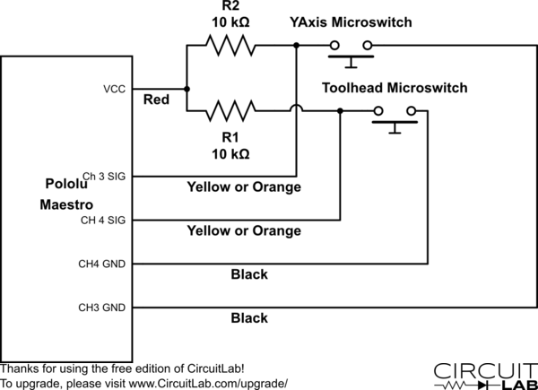
Wire the microswitches as shown in this diagram. I used servo extension cables and the colors mentioned reflect that. Note that the signal wire could also be white.
The 5V connection to the Maestro is not the one on the servo connectors. There is a separate 5V and GND along the top edge. See this section of the Maestro user’s guide for details.
Solder a two pin header onto the pads for the 5V and GND. Use the two way molex connector and 0.1 inch pins to create a connector to plug onto the header. Note that the ground pin is not used, instead the ground on the servo connectors is used.

Jack the Ripper Bot II – Mechanics
Sep 4th
Part I covered the introduction to the robot. This part covers the mechanical assembly.
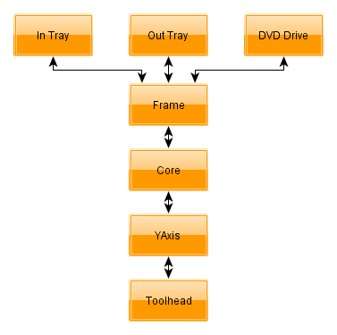
I divided the mechanical design into several groups, which I will refer to throughout. These names are also used for the part designs.
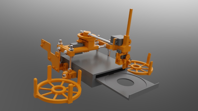
The frame holds everything together. It attaches to the DVD drive. Onto the frame is the in and out trays and what I call the “core”. The core is the main pivoting mechanism for the arm that loads and unloads discs.
At the end of the arm is the YAxis which raises and lowers discs. This should have been called the ZAxis but C’est la vie…
Finally the toolhead is at the bottom of the YAxis and grabs and releases discs.
General Notes
I printed all parts in PLA with three perimeters and 20% fill.
No support is required. The STLs are already correctly orientated.
Any STL name ending in _X2.stl means print two copies of that part.
Whereever M8 nuts are used always use a M8 lock washer against the nut, unless the nut goes into a nut trap.
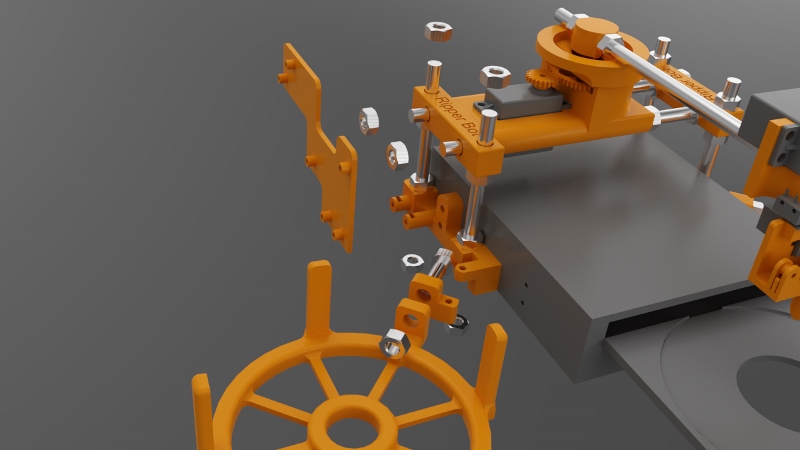
Exploded diagrams don’t show M8 lock washers, M3 hardware or M2 hardware.
Filing of the printed parts may be needed, especially for the M2 nut traps and if the first layer has a lip because it was squashed.
If you are unsure about any step you can download a 3D PDF of the entire robot. Open in Adobe Reader and click on the image. You can then spin the model around and zoom in to examine it from every angle.
1. DVD Drive
The DVD drive must be an internal 5.25 inch type designed to be used horizontally. The tray electronics must open and close the tray fully by pressing the front button on the drive. When the tray is open it must be possible to lower a disc into the tray vertically. I.e. make sure the front of the drive does not overhang the back of the tray slightly.
2. Frame
Attach the left and right brackets onto the drive using M3x12 bolts and the rear mounting holes in the drive case. The curved ends go towards the rear.
Attach the tray anchors to the left and right brackets using M3x18mm bolts. M3 nuts go into the recesses on the bottom of the tray anchors.
Attach the in and out trays to the tray anchors. Use M8x30mm threaded rod, M8 nuts and M8 lock washers. The out tray has slightly sloping sides at the top. The in tray does not.
Attach the electronics caddy to the left bracket using two M3x14mm bolts. Put M3 nuts into the nut traps.
Attach the four M3x100mm threaded rods to the left and right brackets. M8 nuts are placed into the recesses in the bottom of the brackets.
Attach the corners to the threaded rods you just added. They should be positioned as close as possible to the top of the threaded rods.
3. Core
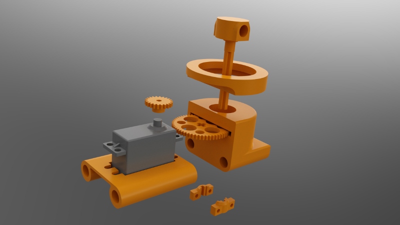
Attach the GWS S125 1T servo to the servo bracket. The end of the servo with the shaft must go to the end of the servo bracket that is built up underneath. Use four M3x14mm bolts with M3 washers next to the bolt heads.
Press the servo gear onto the shaft of the servo. It will be a tight fit. Note that there are three servo gears. Use the “core” servo gear.
Press a 608ZZ bearing into the recesses in the top and bottom of the gear housing.
Slide the main gear into the slot in the gear housing.
Press the hub into the gear housing so that it goes through the upper 608ZZ bearing, the main gear and then the lower 608ZZ bearing. Make sure it is all the way in. It will be a tight fit. If you can’t make it fit through the gear then carefully file the hole in the gear, but do not overfile.
Attach the hub retainers to the bottom of the hub. These clamp onto the cross-shaped part of the hub. Use two M3x16mm bolts with nuts. It should be close to the bottom of the gear housing without touching it.
Place the support ring on top of the gear housing.
Slide two M8x200mm threaded rods through the left corner, servo bracket, gear housing and right corner. The order should be (from left to right):
M8 nut, M8 lock washer, left corner, servo bracket, gear housing, M8 lock washer, M8 nut, M8 nut, M8 lock washer, right corner, M8 lock washer, M8 nut.
4. YAxis
Press the servo gear onto the Futaba S3003 servo (modified for continuous rotation). The fit will be tight. Be sure to use the servo gear for the Y axis.
Slide the servo down into the Y axis. The tabs on the servo go towards the front of the Y axis.
Push the rod up into the Y axis from the bottom. When it reaches the servo gear you will have to move the servo up and down a bit to get the rod to slide in. You can also carefully turn the servo by hand.
Attach the servo to the Y axis using four M3x14mm bolts. Use M3 washers next to the bold heads.
Attach the microswitch without a roller to the side of the Y axis using M2x14mm bolts. Put M2 nuts into the nut traps. Use the image above to orientate the microswitch.
Attach the Y axis to the core using a M8x220mm threader rod. A M8 nut goes into the nut trap on the underneath of the Y axis. The order should be (from front to back):
M8 nut (in nut trap), Y axis, M8 lock nut, M8 nut, M8 nut, M8 lock nut, hub, M8 lock nut, M8 nut
5. Toolhead
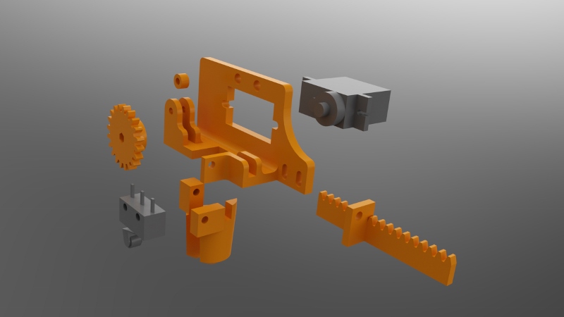
Screw the 9g micro servo to the back of the frame using two M2x10mm bolts.
Attach the guide which goes between the two forks using a single M2x10mm bolt.
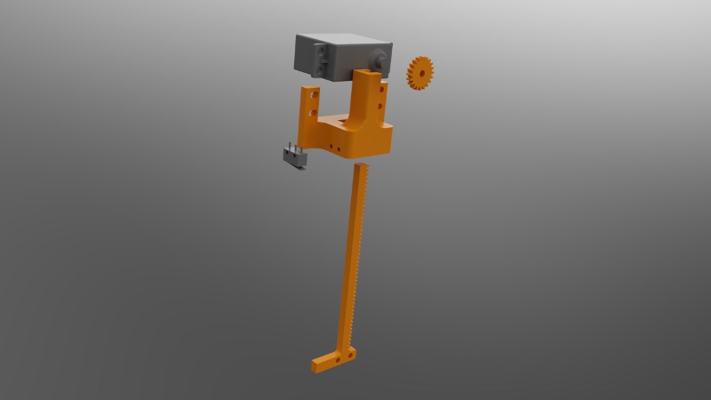
Slide the rack into position.
Press the servo gear onto the servo shaft. It will be a tight fit. The teeth on the gear should mesh with the teeth on the rack.
Attach the fixed gripper to the frame using a M2x10mm bolt.
Attach the moving gripper to the rack using a M2x10mm bolt.
Attach the microswitch with the roller to the frame using two M2x10mm bolts.
Attach the toolhead to the bottom of the rod on the Y axis using two M3x14mm bolts.

Jack the Ripper Bot I – Introduction
Sep 3rd
I had a problem.
Over the last 15 years my wife has amassed a huge DVD collection and we don’t have enough space for shelving to access them all. About a year and a half ago I decided to start ripping the discs to a media server. This went well initially but it was tedious. Ripping is a slow business and every hour I had to feed the computer another disc which was disruptive to normal life. I gave up.
Recently inspired and armed with a 3D printer I decided to build a robot to perform the disc changing. Jack the Ripper Bot was born.
View the video of the robot in action: http://www.youtube.com/watch?v=mmHycIOtYHA
I will divide the description of Jack into five parts: introduction, mechanics, electronics, software and troubleshooting.
My aims were:
- Modular software and hardware design
- Open source
- Reliable
- Low cost
- Using off-the-shelf electronics
A stack of discs are placed into the “in tray”. An arm moves over to the stack and grabs the top disc. The disc is then lowered into the drive tray. Ripping takes place. Once complete the disc is removed from the drive tray and the arm takes it over to the “out tray” and places it there.
A Raspberry Pi is used to control the robot and a PC is used to control the overall process and the ripping.
I have a laptop which is about four years old and it can rip a DVD in about 1 hour 15 minutes. The in tray is designed to hold 24 discs to give about 28 hours of ripping time. It is of course possible to increase the capacity of the in tray and the out tray if your PC is faster than mine.
A complete bill of materials can be downloaded.
All files, including the software and part source files and STLs can be found on github. The files are licensed under GPLv3.

