Interesting Tech Projects
Posts tagged python

Generating a Part Library in Geomagic Design
Jul 5th
Introduction
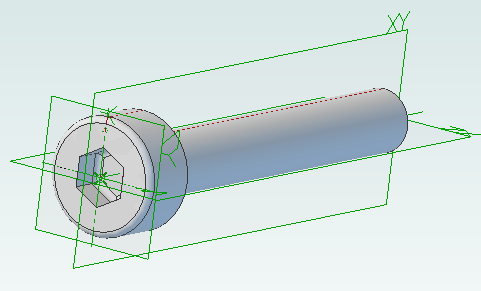
This tutorial demonstrates how to create a library of parts in a CAD neutral format based on a single template part. It takes advantage of parameterization in Geomagic Design.
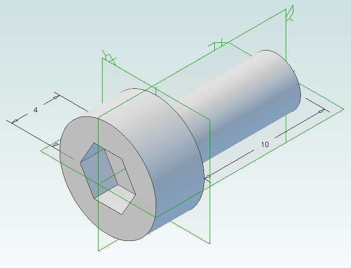
We will start by creating the base part that we will use to create the library. This will be a simple cap head bolt.
Next we will use WizoScript to generate a library of 10 bolts of different lengths.
This type of task is ideally suited to scripting because it handles the tedious repetitive operations needed. While the part demonstrated in this tutorial is simple the same principles can easily be used for complex parts with multiple parameters.
Creating the Template Part
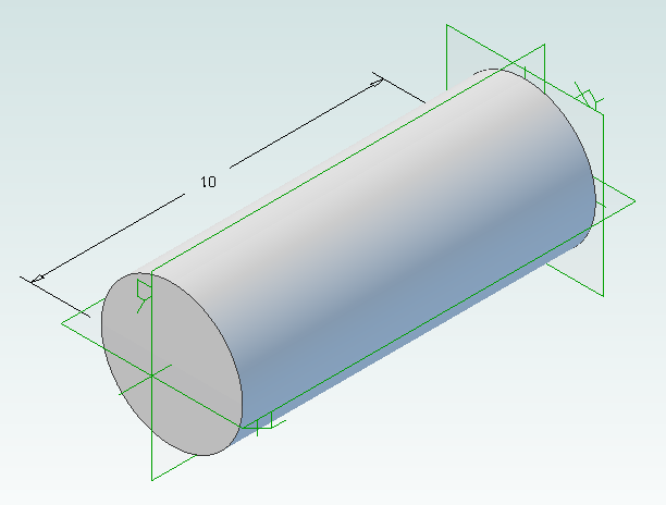
In Geomagic Design create a new part and then a sketch on the XY-Plane. On this sketch draw a circle centered on the origin with a diameter of 4mm and then extrude into a cylinder with a length of 10mm.
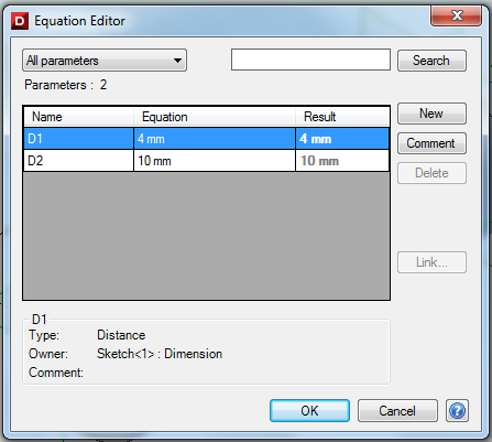
Under the Viewing and Analysis tab click on the Equation Editor button.
Double-click on “D2” and enter “Length” to give the length of the bolt a useful name then close the equation editor window.
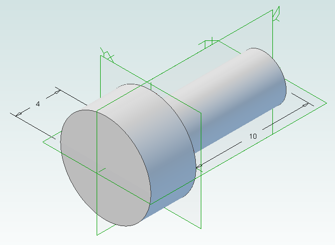
Create the bolt head by adding a sketch to the end of the cylinder on the XY-Plane, setting the diameter to 8mm and extruding 4mm.
Create a new sketch on the top of the bolt head, draw a hexagon with an inside diameter of 4mm and then extrude cut 2mm.
Create a new folder called “PartLibrary” and save as TemplatePart.AD_PRT. Keep the part open in Geomagic to continue with the tutorial.
Writing a Basic Script
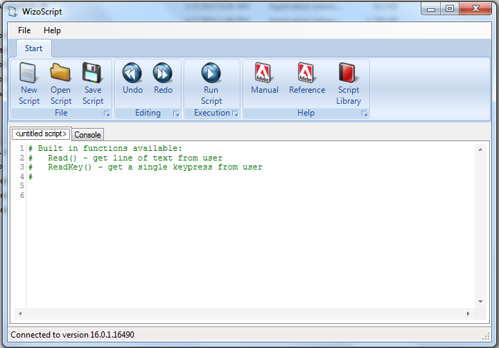
Start WizoScript 1.70 or later. When it runs it automatically creates an empty script that we can start using right away.
First we need to tell the script about our template part. For this tutorial the part must be open in Geomagic when the script runs, however it is possible to use a saved part that is not currently open. Please see the WizoScript reference manual for further details.
The following script line tells WizoScript “I have a part open and I want you to use it”:
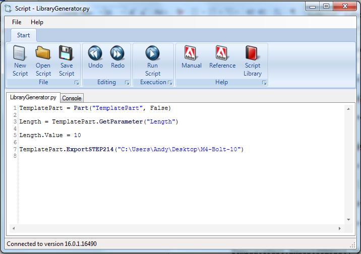
TemplatePart = Part(“TemplatePart”, False)
Next we need to get access to the length parameter that we have already created it. Once we have access to it we can change its value
Length = TemplatePart.GetParameter("Length")
The default units for a script are millimeters, so if we enter the following:
Length.Value = 10
Then we are setting the length of the bolt to 10mm. Enter this into the script.
Now that we have set the length of the bolt we need to export it in a CAD-neutral formal so it can be shared with others. Here is how to do it:
TemplatePart.ExportSTEP214("C:\Users\Andy\Desktop\M4-Bolt-10")
This is what you should have so far:
Save the script and click on the Run button. If there are any errors correct them in the script and try again. If the script is successful you should now have a M4-Bolt-10.stp file.
Generating Multiple Parts
So far it’s not very interesting. We’ve generated a single STEP part that we could have easily created directly in Geomagic Design without needing scripting. Now we will look at generating multiple parts in one go.
The first step is to create a function that is given a length and creates a STEP file. A function is a way of grouping parts of a script together so they can be run over and over again. Edit your script to look like the following:
def GenerateBolt(NewLength):
  Length.Value = NewLength
  TemplatePart.ExportSTEP214("C:\Users\Andy\Desktop\M4-Bolt-"+str(NewLength))

TemplatePart = Part("TemplatePart", False)

Length = TemplatePart.GetParameter("Length")

GenerateBolt(10)
GenerateBolt(12)
We now have a function called GenerateBolt that takes a length and creates a STEP file. The function has to be defined before it is used so put it at the start of the script.
Another key change is that the name of the STEP file contains the length, whatever that may be. This is achieved by appending “M4-Bolt-“ with the length value.
Run the script. It will call GenerateBolt twice and create two STEP files containing a 10mm bolt and a 12mm bolt.
The final step is to create a loop that goes from a minimum length to a maximum length creating bolts. Replace the two calls to GenerateBolt with the following:
MinimumLength = 10
MaximumLength = 20
for NewLength in range(MinimumLength, MaximumLength + 1):
  GenerateBolt(NewLength)
Run the script and it will generate bolts with lengths from 10mm to 20mm.
Here is the final script with comments added to explain:
# Takes a template bolt and creates a library of bolts of different lengths in
# a CAD neutral format

# Creates a bolt of a specific length. NewLength = desired length of bolt in mm
# Saves the bolt to the desktop as a STEP file
def GenerateBolt(NewLength):
  Length.Value = NewLength
  TemplatePart.ExportSTEP214("C:\Users\Andy\Desktop\M4-Bolt-" + str(NewLength))

# Get access to currently opened part that we will used as a template
TemplatePart = Part("TemplatePart", False)

# The template part has a Length parameter defined which we will control
Length = TemplatePart.GetParameter("Length")

# Create bolts from 10mm to 20mm
MinimumLength = 10
MaximumLength = 20
for NewLength in range(MinimumLength, MaximumLength + 1):
  GenerateBolt(NewLength)

Interactive Mobius Strip Generator for Geomagic Design
Jun 29th
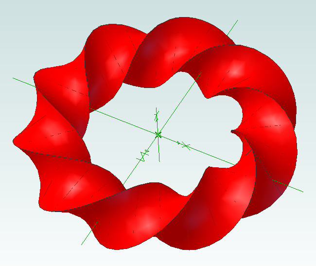
This mini tutorial shows how to generate custom Mobius strips with minimum effort. It demonstrates that python scripting can be used to ask the user for information and then apply it to a part the user is already working on. Hopefully that will be useful to some people when solving problems.
1. Download and install WizoScript 1.70 or later and start it.
2. Start Geomagic Design V16 hotfix 1 (16.0.1.16490) or later.
3. Create a new part and set the units to millimeters.
4. Create a new sketch on the XY plane.
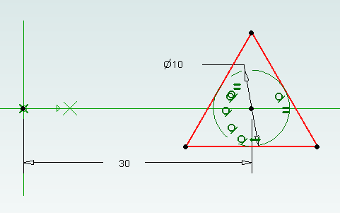
5. Draw a triangle centered on the X axis and set the size of the reference circle to 10mm.
6. Set the center of the triangle 30mm from the origin and exit sketch editing mode.
7. Go to the WizoScript script library and copy the Interactive Mobius Strip Generator. Paste it into WizoScript. Hint: double-clicking on the script in the web-page selects the entire script.
8. Run the script.
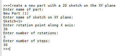
9. You will be asked for the name of the part. Assuming you haven’t saved it enter “New Part (1)”. Then you will be asked for the name of the sketch. Enter “Sketch<1>”.
10. Next you will be asked the rotation point along the X axis. Enter “30”. This puts the rotation point at the center of the triangle.
11. You will be asked for the number of rotations. This is the number of times the mobius strip will completely rotate. Enter “3”.
12. Finally you will be asked to enter the number of steps. Enter “30”.
Now the mobius strip will be generated. Be patient as this can take several minutes. Here is what you should have:
Now it’s time to experiment! You can change the shape of the sketch to create different effects. Setting the rotation point closer or further away from the origin will create a “corkscrew” effect. You can increase or decrease the number of rotations. Reducing the number of steps will make the part faster to create but you might have to manually add a guide curve to get a true mobius strip.
Using this script it is possible to run it multiple times on the same part. For example create two sketches, run it on the first sketch and then run it on the second sketch to create two Mobius strips that are intertwined.

Involute Gears in Alibre Design
Apr 25th
The most common type of gear is the involute gear, which provides smooth and efficient operation. A gear is defined by the following parameters:
- Pitch diameter (diameter of gear)
- Diametral pitch (tooth size)
- Number of teeth
- Pressure angle (commonly 14.5, 20 or 25 degrees)
The pressure angle defines the shape of a tooth. For two gears to mesh the pressure angle and diametral pitch must be the same (i.e. the shape and size of the teeth must match). There is a simple relationship between pitch diameter, diametral pitch and number of teeth so when defining a gear we only need to specify two of those parameters.
The ability to create involute gears is included in python-based ADScript. Let’s see how.
NumberofTeeth = 20
PitchDiameter = 30
PressureAngle = 20

InputGear = Part("Input Gear")
XYPlane = InputGear.GetPlane("XY-Plane")
GearSketch = InputGear.AddGearNP("Gear Profile", NumberofTeeth, PitchDiameter, PressureAngle, 0, 0, XYPlane)
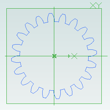
This script creates a new part called Input Gear and then adds a sketch to it on the XY-plane for the profile of a gear by calling AddGearNP. NP shows which two parameters are used, N = number of teeth and P = pitch diameter.
The 0, 0 defines the coordinates of the center of the gear.
Once the gear has been created we can read out the diametral pitch:
DiametralPitch = GearSketch.DiametralPitch
There are two other functions that we can call to create gears, depending on which two parameters we wish to use.
GearSketch1 = MyPart.AddGearDN("Gear Profile", DiametralPitch, NumberofTeeth, PressureAngle, 0, 0, XYPlane)
PitchDiameter = GearSketch1.PitchDiameter

GearSketch2 = MyPart.AddGearDP("Gear Profile", DiametralPitch, PitchDiameter, PressureAngle, 0, 0, XYPlane)
NumberofTeeth = GearSketch2.NumberofTeeth
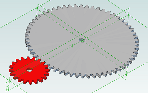
Here is an example script that shows how we can create two gears that can be used together to provide a 3:1 reduction ratio:
# all values are in millimeters
Units.Current = UnitTypes.Millimeters

# pressure angle has to be the same for both gears
# common values are 14.5, 20 and 25
# larger pressure angle = stronger teeth
PressureAngle = 20

# thickness of gears
Thickness = 2
# shaft diameter
ShaftDiameter = 5

# define input gear - 20 teeth and 30mm pitch diameter
Gear1Teeth = 20
Gear1Diameter = 30

# create input gear using number of teeth and pitch diameter
Gear1Part = Part("Input Gear")
Gear1 = Gear1Part.AddGearNP("Gear Profile", Gear1Teeth, Gear1Diameter, PressureAngle, 0, 0, Gear1Part.GetPlane("XY-Plane"))
Gear1.AddCircle(0, 0, ShaftDiameter, False)
Gear1Part.AddExtrudeBoss("Gear", Gear1, Thickness, False)

# diametral pitch must be the same for both gears as this defines tooth size
# use diametral pitch for output gear from input gear calculated value
Gear2DiametralPitch = Gear1.DiametralPitch

# we want a ratio of 1:3 so output gear has three times the number of teeth
Gear2Teeth = Gear1Teeth * 3

# create output gear using number of teeth and diametral pitch
Gear2Part = Part("Output Gear")
Gear2 = Gear2Part.AddGearDN("Gear Profile", Gear2DiametralPitch, Gear2Teeth, PressureAngle, 0, 0, Gear2Part.GetPlane("XY-Plane"))
Gear2.AddCircle(0, 0, ShaftDiameter, False)
Gear2Part.AddExtrudeBoss("Gear", Gear2, Thickness, False)

# get the calculated pitch diameter of the output gear
Gear2Diameter = Gear2.PitchDiameter

# calculate distance between gear centers so we know how far apart the shafts need to be
print "Distance between gear centers = %fmm\n" % ((Gear1Diameter + Gear2Diameter) / 2)
And the result:

Scripting Metric Screws in Alibre Design
Apr 10th
Creating screws is tedious. There are lots of diameter and length combinations and there is more to a screw than first meets the eye. Creating a parts library containing lots of variations is a perfect use for ADScript.
Here is a M3 x 20mm socket cap screw generated from the script below.
This screw is modeled to the ISO 4762 standard. Notice the threads are missing? Modeling the threads is generally a waste of time and resources as the aim is to ensure a screw fits, is long enough and there is enough clearance to install it.
# Creates a metric socket cap screw using ISO 4762
# See: http://practicalmaintenance.wordpress.com/2009/01/30/socket-head-cap-screws-article-13/

# Size of screw
Diameter = 3.0
Length = 20.0

# Measurements table containing H, F, E, T, C from web page
MetricData = {}
MetricData[1.6]  = [3.14,  2.0,  1.73,  0.7,  0.16]
MetricData[2.0]  = [3.98,  2.6,  1.73,  1.0,  0.2]
MetricData[2.5]  = [4.68,  3.1,  2.3,   1.1,  0.25]
MetricData[3.0]  = [5.68,  3.6,  2.87,  1.3,  0.3]
MetricData[4.0]  = [7.22,  4.7,  3.44,  2.0,  0.4]
MetricData[5.0]  = [8.72,  5.7,  4.58,  2.5,  0.5]
MetricData[6.0]  = [10.22, 6.8,  5.72,  3.0,  0.6]
MetricData[8.0]  = [13.27, 9.2,  6.86,  4.0,  0.8]
MetricData[10.0] = [16.27, 11.2, 9.15,  5.0,  1.0]
MetricData[12.0] = [18.27, 13.7, 11.43, 6.0,  1.2]
MetricData[16.0] = [24.33, 17.7, 16.0,  8.0,  1.6]
MetricData[20.0] = [30.33, 22.4, 19.44, 10.0, 2.0]
MetricData[24.0] = [36.39, 26.4, 21.73, 12.0, 2.4]
MetricData[30.0] = [45.39, 33.4, 25.15, 15.5, 3.0]
MetricData[36.0] = [54.46, 39.4, 30.85, 19.0, 3.6]
MetricData[42.0] = [63.46, 45.6, 36.57, 24.0, 4.2]
MetricData[48.0] = [72.46, 52.6, 41.13, 28.0, 4.8]
MetricData[56.0] = [84.54, 63.0, 46.83, 34.0, 5.6]
MetricData[64.0] = [96.54, 71.0, 52.53, 38.0, 6.4]

CapDiameter = MetricData[Diameter][0]
FilletTransitionDiameter = MetricData[Diameter][1]
HexHoleDiameter = MetricData[Diameter][2]
HexHoleDepth = MetricData[Diameter][3]
RimFilletRadius = MetricData[Diameter][4]

# all values are in millimeters
Units.Current = UnitTypes.Millimeters

# Create part
Screw = Part("Cap Screw M%dx%d" % (Diameter, Length))

# body
Profile = Screw.AddSketch("Profile", Screw.GetPlane("XY-Plane"))
Profile.AddLines([0, 0, 0, CapDiameter / 2, Diameter, CapDiameter / 2, Diameter, Diameter / 2, Diameter + Length, Diameter / 2, Diameter + Length, 0, 0, 0], False)
Screw.AddRevolveBoss("Body", Profile, Screw.GetAxis("X-Axis"), 360)

# hex hole
HexHole = Screw.AddSketch("Hole", Screw.GetFace("Face<5>"))
HexHole.AddPolygon(0, 0, HexHoleDiameter, 6, False)
Screw.AddExtrudeCut("Hex Hole", HexHole, HexHoleDepth + ((FilletTransitionDiameter - Diameter) / 2.0), True)

# fillet from cap to shaft
Screw.AddFillet("Cap Joint", Screw.GetEdge("Edge<21>"), (FilletTransitionDiameter - Diameter) / 2.0, False)
# fillet at bottom of hex hole
Screw.AddFillet("Hex Hole Bottom", [Screw.GetEdge("Edge<5>"), Screw.GetEdge("Edge<9>"), Screw.GetEdge("Edge<12>"), Screw.GetEdge("Edge<21>"), Screw.GetEdge("Edge<18>"), Screw.GetEdge("Edge<15>")], (FilletTransitionDiameter - Diameter) / 2.0, False)
# fillet on rim
Screw.AddFillet("Cap Rim", Screw.GetEdge("Edge<35>"), RimFilletRadius, False)

Python Scripting with Alibre Design
Apr 3rd
ADScript makes it easy to use Alibre Design with Python scripting. For example creating a new part:
Test = Part("Test")
We can get access to planes in the design workspace, for example:
XYPlane = Test.GetPlane("XY-Plane")
Once we have a part and plane we can create a sketch on the plane:
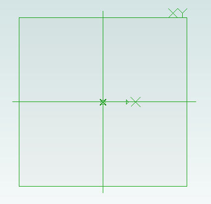
MySketch = Test.AddSketch("MySketch", XYPlane)
Adding to the sketch is easy:
MySketch.AddCircle(0, 0, 10, False)
Now we can extrude it:
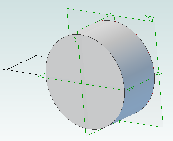
Object = Test.AddExtrudeBoss("Object", MySketch, 5, False)

Python CAD Scripting
Jun 24th
FreeCAD supports Python as a scripting language which allows the creation of 3D parts based on variables. This is great for building libraries which support customizable part creation.
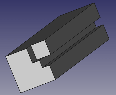
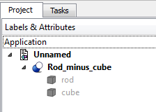
As a first attempt I created the following test script. When executed in FreeCAD 0.13 it creates a rod 10mm x 10mm x 50mm with a notch in it. It then removes a cube measuring 4mm x 4mm x 4mm from one end.
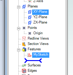
Here is what the hierarchy looks like:
And here is the script:
import FreeCAD, FreeCADGui, Part

App = FreeCAD

doc = App.activeDocument()

rodbasepts = list()
rodbasepts.append(App.Vector(0, 0, 0))
rodbasepts.append(App.Vector(0, 10, 0))
rodbasepts.append(App.Vector(10, 10, 0))
rodbasepts.append(App.Vector(10, 0, 0))
rodbasepts.append(App.Vector(6, 0, 0))
rodbasepts.append(App.Vector(6, 2, 0))
rodbasepts.append(App.Vector(4, 2, 0))
rodbasepts.append(App.Vector(4, 0, 0))
rodbasepts.append(App.Vector(0, 0, 0))
rodbase = Part.makePolygon(rodbasepts)
rodbasefilled = Part.Face(rodbase)
rod = rodbasefilled.extrude(App.Vector(0, 0, 50))
#rod.Placement = App.Placement(App.Vector(10, 0, 0), App.Rotation(0, 0, 0, 1))
rodpart = doc.addObject("Part::Feature", "rod")
rodpart.Shape = rod

cubebasepts = list()
cubebasepts.append(App.Vector(0, 0, 0))
cubebasepts.append(App.Vector(0, 4, 0))
cubebasepts.append(App.Vector(4, 4, 0))
cubebasepts.append(App.Vector(4, 0, 0))
cubebasepts.append(App.Vector(0, 0, 0))
cubebase = Part.makePolygon(cubebasepts)
cubebasefilled = Part.Face(cubebase)
cube = cubebasefilled.extrude(App.Vector(0, 0, 4))
cubepart = doc.addObject("Part::Feature", "cube")
cubepart.Shape = cube

cut = doc.addObject("Part::Cut", 'Rod minus cube')
cut.Base = rodpart
cut.Tool = cubepart
rodpart.ViewObject.hide()
cubepart.ViewObject.hide()
doc.recompute()
To use create a new Part and then copy and paste the script into the Python Console inside FreeCAD.
