Interesting Tech Projects
Posts tagged hardware

Change in Direction
Mar 22nd
I decided that the McWire CNC machine probably wouldn’t be able to product the accuracy I need, or have the lifespan that I need for a machine. In addition I want to be able to cut objects up to a square foot in size. The McWire design would need to be four square feet in size to be able to do that. Instead I decided to buy a machine kit.
I was drawn to the Fireball CNC designs because they are individually hand made and affordable. They also use a gantry design which results in a footprint not much larger than the cutting size. The problem was that they didn’t make a machine that could cut one square foot objects. Until now that is…
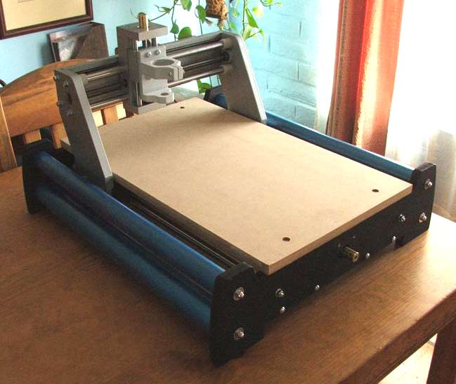
Fireball CNC have just released the V90, which has a cutting area of around 12″ x 18″ x 3″. I was fortunate enough to get one during the beta testing phase. Below is a picture of the assembled machine.
The next steps are to extend the motor wires, attach them and test jogging from EMC2.
CNC Update
Jan 11th
The project was paused for Christmas and New Year, now I’m wondering whether to continue with the McWire design or go with something else. I recently came across the Fireball CNC machine, which looks very nice. Each machine is hand made in the US, which appeals to me.
One of the early projects I wish to work on is a clock and I found some nice clocks with plans for sale. I contacted the designer and the largest part in the design I am interested in is a cog with a diameter of 11 1/2″. This is too big for the Fireball CNC machine.
So, looking at the McWire design, in order to cut parts 12″ by 12″, the machine would need to have a footprint of at least 24″ x 24″. The design isn’t a compact one. So I am currently undecided what to do. Unless I find a design that really looks appealing I may continue with the McWire design.
My recommendation for anyone wanting to build a CNC machine is to think carefully about how large the parts are that they want to make, then pick a design that fits that requirement.
Bearings
Nov 27th
I’ve found what looks like a good source for bearings for the design. It’s Skate Bearings and they sell individually as well. Price seem very reasonable. If I can’t find a local skate shop then I will probably order from them.
Power Supply
Nov 23rd
The Yahoo group for the HobbyCNC boards contains a file which describes a linear, unregulated 10A power supply, suitable for driving four motors. This power supply converts 120VAC to 34VDC up to 10A. The circuit diagram is very simple, but a lot of additional effort and parts are required to construct a working power supply.
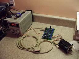
Here is a picture of my completed power supply connected to three motors:
As you can see, the power supply sits in a box with the HobbyCNC board. Currently the lid is missing, as are the ventilation holes. Also the motors are simply connected to the board rather than via eight conductor cable that goes through holes in the side of the case.
I am not going to reproduce a circuit diagram here because I don’t want the liability issues of publishing a circuit diagram that involves lethal voltages. If you own a HobbyCNC board then you can get the circuit diagram (and warnings) from the files section of the Yahoo group, otherwise you can find plenty of designs using Google. In general however the power supply should match the requirements of the control board you are using, and the vendor of the control board should be able to suggest a ready-made power supply or a circuit diagram for one.
All information in this posting is for reference only. Anyone who uses this information assumes all risks. The voltages involved can kill and all necessary precautions should be taken. In addition a large capacitor is used which can keep the voltages high for a period after the power is turned off. The power supply should not be run with the lid off and all exposed metal parts inside and outside of the power supply should be grounded. For this reason I chose to use a grounded power cable rather than the cheaper two prong design. If you are not proficient with using mains voltages you are better off just buying a suitable power supply. I do not claim or guarantee that any parts I have used are suitable for this purpose. All information is provided “as is” and without waranty. Y0u have been warned…
The power comes in to the board via a standard power cord and is connected through a 4A fuse to a rocker switch. After the rocker switch is the 10A transformer than produces 24VAC. This is then fed into a AC to DC converter board to produce 34VDC. The DC voltage then goes through a 10A fuse to the HobbyCNC board.
Here is a view of the rocker switch and the two panel mounted fuse holders:
The transformer, AC to DC board and the HobbyCNC board are all bolted down to the bottom of the case using bolts. I added 1/4″ spacers below each to lift the boards up off the bottom of the case. I positioned the HobbyCNC board up against the edge of the case and cut a rectangular hole for the PC connector. This fits snugly giving a nice finish:
The AC to DC board is made of stripboard (prototype board with copper strips), and contains the recitifer, capacitor and resistor. I wanted to make the construction modular so I used wire connectors to connect the various components (transformer, AC to DC board, fuses, switch, HobbyCNC board, power cord) together. This allows me to easily replace any component when needed.
Still to do is the lid, an emergency stop switch and some ventilation holes.
Bill of Materials (read the disclaimer at the start of this post!):
1x 24V 10A Transformer LP-520, MPJA.com #7846TR, $17.99
1x 27000uF Electrolytic Capacitor, Digi-key #P10021-ND, $11.72
1x 2kOhm, 1W 5% Metal Oxide Resistor, Digi-key #2.0KW-1-ND, $0.15
1x 35A, 600V Bridge Rectifier Wire Leads, Digi-key #MB356W-BPMS-ND, $5.00
1x DPST 16A Rocker Switch, Digi-key #CH784-ND, $1.46
1x 16AWG 3 Conductor Power Cord 79″, Digi-key #Q110-ND, $5.43
2x 3AG Panel Mount Fuseholder, Digi-key #F005-ND, $6.10
1x 4A 250V Fuse, Digi-key #283-2023-ND, $0.48
1x 10A 250V Fuse, Digi-key #283-2622-ND, $0.57
1x 14AWG Wire Red 2ft, Local, $0.46
1x 14AWG Wire Black 2ft, Local, $0.46
1x 14AWG Wire Brown 2ft, Local, $0.46
1x Heat Shrink Tubing Assorted Sizes, Local, $2.99
4x #4 x 3/4″ Bolt, Local (Ace Hardware), $0.28
4x #4 Nut, Local (Ace Hardware), $0.24
4x #4 Washer, Ace Hardware), $0.24
4x #4 1/4″ Spacer, Local (Ace Hardware), $2.32
8x #6 x 3/4″ Bolt, Local (Ace Hardware), $0.56
8x #6 Nut, Local (Ace Hardware), $0.48
8x #6 1/4″ Spacer, Local (Ace Hardware), $2.32
15x #6 Washer, Local (Ace Hardware), $0.90
1x #6 External Tooth Washer, Local (Ace Hardware), $0.08
1x Stripboard, Local, $3.49
1x 20 Pack Wire Connectors 600V, Local (Home Depot), $1.99
Total cost: $66.17
Not included: soldering iron, solder, shipping costs, taxes on local purchases.
Note that the shipping cost for the transformer was $10.51.
The total cost including taxes and shipping was probably closer to $85. A ready-made power supply can probably be purchased for $110 plus shipping, so perhaps it didn’t save very much.
Missing from the list is the case. That is because I managed to salvage an old index card drawer and holder. I threw the drawer away and carved up the holder to make the case. This cost me $2 from World Care. A brand new plastic case will cost around $30 from Digi-key or Mouser.
The cost of the power supply is not insignificant. When people post low cost CNC designs they love to indicate how cheap the project is but omit important details like the power supply. If you want motors with a good amount of torque then a good sized power supply is also required.
Windows XP and Stepper Motors
Nov 4th
My first test after assembling the board was to connect one motor to each axis in turn and test using Windows XP SP2 and Mach3. The test involved going to the motor tuning section and pressing the up and down arrows.
On the X and Y axis it was clear that steps were being lost. I had to turn the settings down to the lowest speed and even then there was the occasional loss of a step.
On the Z axis however the shaft only twitched. With identical settings to the X and Y axis it would not spin. So, the conclusion I drew was that there is a board problem with the Z axis.
Now I am testing with EMC2 running on Linux. My first test showed that all three axis, X, Y and Z appear to work just fine. The shaft spins quite happily on the Z axis…
So the moral of the story is that if one axis behaves differently it could be Windows causing it and not the board.
If you are stuck with Windows probably the only ways to determine where the problem lies are to either use a modified cable to swap pins around (so the problem axis is controlled by the pins for another axis) or to switch to TurboCNC and try that (perhaps with FreeDOS).
Testing EMC2/LinuxCNC on Ubuntu 7.10 Gutsy
Nov 3rd
I just completed the first test of running EMC2/LinuxCNC on Ubuntu with the HobbyCNC board. I connected a motor to the X-axis and started EMC2 with the “Axis” interface. I then told it to execute the default G-code file it loads with. Lo and behold the motor started spinning! I then moved the motor to the Y and Z axis and repeated. Seems to work well.
I didn’t notice any stalling so the problems I experienced with Windows XP and Mach3 must be due to Windows XP…
Here is a video:
Details on how to install EMC2 from source along with RTAI will follow when I have them ready. Also I will post the configuration files for the HobbyCNC board a bit further on in the project when I have more confidence that they are correct.
Basic Motor and Board Testing Completed
Oct 31st
I have completed a basic test of the board and motors. The motors seem to miss steps even at a very low speed, and I think this is either because there is no load on the motor’s shaft or my laptop doesn’t generate the pulses properly (happens with some PCs). Here is what I did (use at your own risk!).
I installed Mach3 and went to Config -> Select Native Units and chose Inches.
I next went to Config -> Ports and Pins -> Motor Outputs Tab and configured the software for the pins that my board uses. I set direction and step to active low. Consult your board documentation for the settings here.
I then connected a single motor to the X axis, set the jumpers on the board for the largest step, connected the board to my PC’s printer port, turned on the power to the board (24VDC regulated from a bench power supply) and clicked on the large Reset button in Mach3.
Currently I only have a 30VDC, 3A bench power supply to use. Because of this I could only connect one motor at a time. Even so this is a prudent thing to do anyway. If you make a mistake then you risk damaging only one of the expensive driver chips.
Next in Mach3 I went to Config -> Motor Tuning and clicked on the X axis button. I entered the following settings:
Steps per: 16000
Velocity: 0.19998
Acceleration: 0.2296875
Step Pulse: 1
Dir Pulse: 0
I then clicked on Save Axis Settings and pressed the up and down arrow buttons. Each press of the buttons caused the motor shaft to turn a little bit. Holding down the button causes it to turn repeatedly. I did see some missed steps but I think this is due to either my PC or the fact that there was no load on the motor.
I then moved the motor to the Y axis and the X axis and repeated the test at each stage, making sure to turn the power off to the board when connecting and disconnecting motors and my PC.
Finally I took the other two motors and connected them to the X axis in turn and repeated the test.
Updates
Oct 24th
I found out that the linux-rt kernel is not suitable for running EMC2/LinuxCNC. Sorry if you followed those steps. You can remove it using sudo apt-get remove linux-rt. Instead the kernel must be patched with RTAI. I’m currently working out the correct steps to do this. So far I tried the pre-built kernel in the Gutsy experimental folder but ethernet was broken. I don’t recommend bothering with those packages. Instead I hope to come up with the steps to install EMC2/LinuxCNC manually.
I have received most of the parts for the 24VDC, 10A power supply that is needed for the HobbyCNC board. Once I have that completed I will post a complete bill of materials with Digi-Key part numbers.
I damaged once of the stepper drivers on my HobbyCNC board while performing some simple tests with a bench power supply I have. The motor was connected incorrectly. Now I have to order a replacement. Luckily I was testing only one axis, otherwise I could have damaged all the drivers.
As you can see slow progress is being made on several fronts. Hopefully I will have something concrete to post soon.
HobbyCNC Kit Arrived!
Oct 18th
The kit arrived and here is a picture of everything received:

Here is a close up of one of the motors:

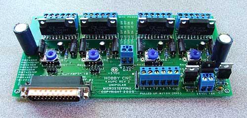
And here is the board assembled (took about 1 1/2 hours):

Now I need to hook it up to a PC and test it with a single motor. I can’t connect all three motors until I have built a 10A power supply. My current supply is only 3A so can’t safely drive more than one motor.
Pitch Conversions
Oct 17th
In order to set up the CNC software we need to know the pitch of the leadscrew being used. I found a Pitch Conversions Table to help with this. I have purchased a 6ft 1/4″-20 (20 threads per inch) threaded rod to use as a leadscrew. According to the table this is a pitch of 1.27mm.
With 200 steps per revolution that will give 6.35um per step. Using 1/16 microstepping that should give an average of 0.397um per microstep. However there will likely be a bit of play between the nut on the leadscrew and the leadscrew, eroding this accuracy somewhat. Also the threaded rod and the motor are made to specific tolerances and are not exact.

