Interesting Tech Projects
Posts tagged fireballcnc
Fireball CNC V90 Limits and Speed
Apr 7th
Yesterday I performed some testing on my Fireball CNC V90. I started off with each axis pretty much centered, to reduce the risk I crash the machine into it’s hard limits (the physical limits of each axis).
Using the full stepping inches configuration I tried:
G00 X1
to move the X axis (the longest axis) one inch. The motor accelerated and then stalled. This results in a nasty whirring/vibrating sound and no movement. A bit like crunching a gear in a manual transmission car. I found the same for the other two axis.
Next I tried moving the axis at slower speeds by specifying the inches per minute (IPM):
G01 F30 X1

G01 F50 X0

G01 F60 X1
etc. I found that I could achieve the following speeds before the motors stalled:
- X: 148 IPM
- Y: 80 IPM
- Z: 33 IPM
Fireball CNC confirmed that Y will operate slower due to the different forces on the rails.
The next step is to try 1/4 stepping. This will result in a lower speed, but will increase the torque, so it should be possible to get a little bit closer to the theoretical maximum speed.
I also measured the following amount of travel for each axis:
- X: 17.85 inches
- Y: 11.7 inches
- Z: 2.75 inches
Since I received my machine Fireball CNC has increased the Z axis travel slightly.
CNC First Steps and Coordinate Systems
Mar 29th
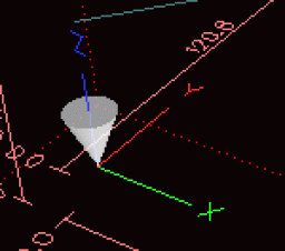
Today I connected the motors to the V90 machine, connected the motors to the HobbyCNC controller board and started EMC2. In the EMC2 interface AXIS the cartesian coordinate system is shown along with the position of the bit, illustrated with a cone:
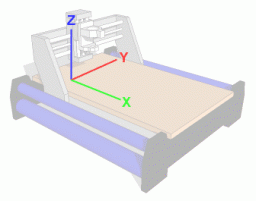
I connected the motors to the board so the following coordinate system would be used on the machine. I picked this system because it seems customary to call the longest axis the X axis. Plus this system makes the most sense to me. However, note that other people may swap the X and Y axis from what I am using here:
Jogging each axis causes the cone (representation of the bil) to move in the display, and at the same time I observed how the machine moved. In AXIS a positive movement in any direction moves the cone towards the letters ‘X’, ‘Y’ and ‘Z’. However on the machine every axis moved in the opposite direction. This meant that I needed to reverse the direction of the motors.
The motor direction is reversed by swapping the ‘A’ and ‘a’ wires. Note that this may not be the case for all motors. Check the documentation that came with your contoller board to be sure.
Once the motors had been reversed the machine movements copied the movement of the cone in AXIS.
The next step was to make sure the machine was moving roughly the correct amount each time. I calculated a configuration (essentially the steps needed to move one inch) for each axis. On the V90 the X and Y axis are 5 threads per inch, but the Z axis is 12 threads per inch. More on how this calculation is performed in a later post. Plugging these values into the EMC2 configuration should do the trick.
I then zeroed the position of each axis in AXIS and used a ruler to measure the location of the Z axis assembly from the side of the gantry, which is the distance the Y axis is moved in from the side. I then jogged the Y axis until the display showed it had moved +0.5 inches. Remeasuring confimed that the Y axis had indeed moved half an inch.
These steps were repeated for the Z axis.
To be sure I also created an EMC2 configuration for the V90 in millimeters and repeated the test. This time I jogged each axis +0.1 x 10 times, to move the axis one millimeter.
Change in Direction
Mar 22nd
I decided that the McWire CNC machine probably wouldn’t be able to product the accuracy I need, or have the lifespan that I need for a machine. In addition I want to be able to cut objects up to a square foot in size. The McWire design would need to be four square feet in size to be able to do that. Instead I decided to buy a machine kit.
I was drawn to the Fireball CNC designs because they are individually hand made and affordable. They also use a gantry design which results in a footprint not much larger than the cutting size. The problem was that they didn’t make a machine that could cut one square foot objects. Until now that is…
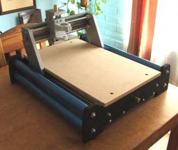
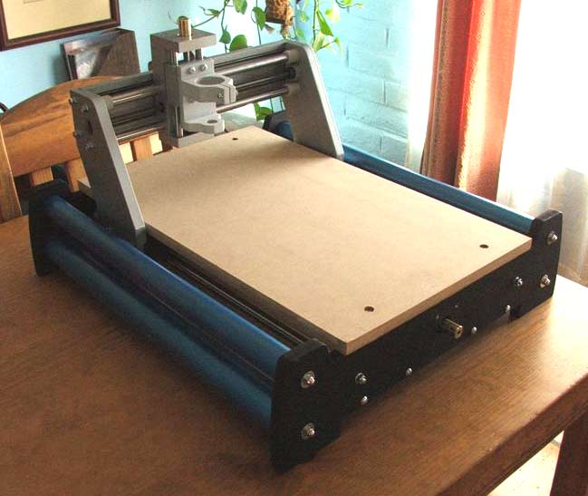
Fireball CNC have just released the V90, which has a cutting area of around 12″ x 18″ x 3″. I was fortunate enough to get one during the beta testing phase. Below is a picture of the assembled machine.
The next steps are to extend the motor wires, attach them and test jogging from EMC2.
