Interesting Tech Projects
Posts tagged CAD

Drum and Banjo Head Tension Gauge
Aug 25th
Measuring the tension on the head of a drum or banjo is important in order to be able to determine if the head is the right tension for your needs. It’s also useful to measure tension that gives a particular tone you like, ensuring you can always get back to the same tension after swapping the head or experimenting.
A commercial gauge is available called a Drum Dial and retails for $60 or more. Here is how I made mine for just a few dollars.
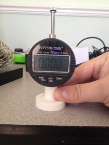
I started off with a cheap Harbor Freight dial indicator. Mine is digital but the analog version would work fine also. These can be picked up for $15 or less with coupons.
Next I added a base. I 3D printed mine but it can also be made out of wood. The spring in the dial indicator is quite weak so I designed the base so that the zero point is one millimeter from maximum spring compression. This ensures that we are using as much spring pressure as the dial indicator can give to press into the head. The base is a friction fit onto the indicator and a tight fit is needed. The bottom of the base has to be completely flat.
Once the base is installed turn on, press down on a flat surface and set to zero. Remove from the surface and apply a few times to make sure the zero point is always found.
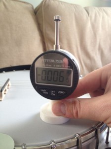
Now press down on the drum or banjo head to measure the head tension. The Drum Dial comes with a spacer to help keep measurements away from the tension hoop. I decided to eyeball it instead.
The values obtained can’t be compared with a Drum Dial or other DIY tension gauges because the result is dependent on the strength of the spring however Drum Dials use a scale that sets 100 to the highest tension. To convert the dial indicator value to the same scale:
- 0.000″ = 100
- -0.001″= 99
- -0.002″ = 98
- …
- -0.010″ = 90
The 3D printed base used three shells, 20% infill, took about one hour and cost about $0.40 in plastic.
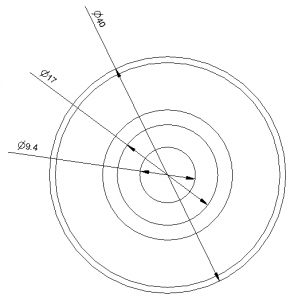
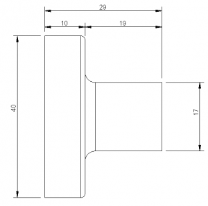
Here are the dimensions of the base for making your own. All dimensions are in millimeters.

Generating a Part Library in Geomagic Design
Jul 5th
Introduction
This tutorial demonstrates how to create a library of parts in a CAD neutral format based on a single template part. It takes advantage of parameterization in Geomagic Design.
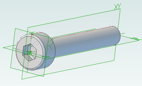
We will start by creating the base part that we will use to create the library. This will be a simple cap head bolt.
Next we will use WizoScript to generate a library of 10 bolts of different lengths.
This type of task is ideally suited to scripting because it handles the tedious repetitive operations needed. While the part demonstrated in this tutorial is simple the same principles can easily be used for complex parts with multiple parameters.
Creating the Template Part
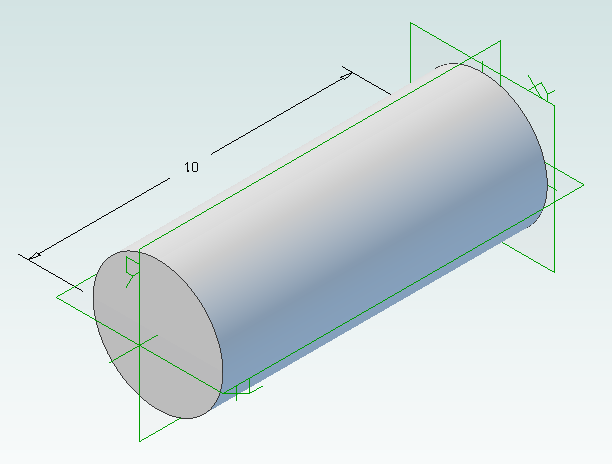
In Geomagic Design create a new part and then a sketch on the XY-Plane. On this sketch draw a circle centered on the origin with a diameter of 4mm and then extrude into a cylinder with a length of 10mm.
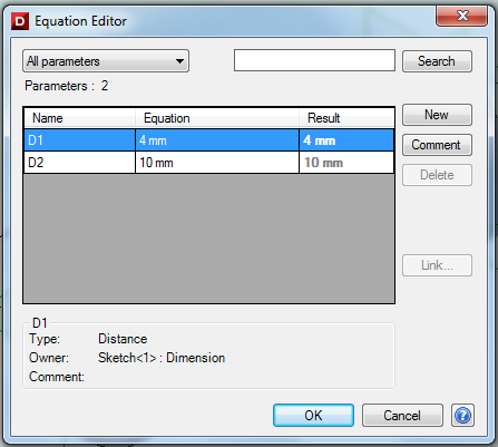
Under the Viewing and Analysis tab click on the Equation Editor button.
Double-click on “D2” and enter “Length” to give the length of the bolt a useful name then close the equation editor window.
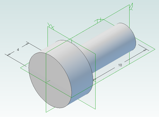
Create the bolt head by adding a sketch to the end of the cylinder on the XY-Plane, setting the diameter to 8mm and extruding 4mm.
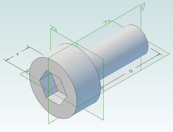
Create a new sketch on the top of the bolt head, draw a hexagon with an inside diameter of 4mm and then extrude cut 2mm.
Create a new folder called “PartLibrary” and save as TemplatePart.AD_PRT. Keep the part open in Geomagic to continue with the tutorial.
Writing a Basic Script
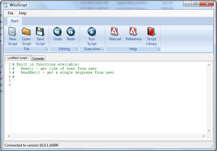
Start WizoScript 1.70 or later. When it runs it automatically creates an empty script that we can start using right away.
First we need to tell the script about our template part. For this tutorial the part must be open in Geomagic when the script runs, however it is possible to use a saved part that is not currently open. Please see the WizoScript reference manual for further details.
The following script line tells WizoScript “I have a part open and I want you to use it”:
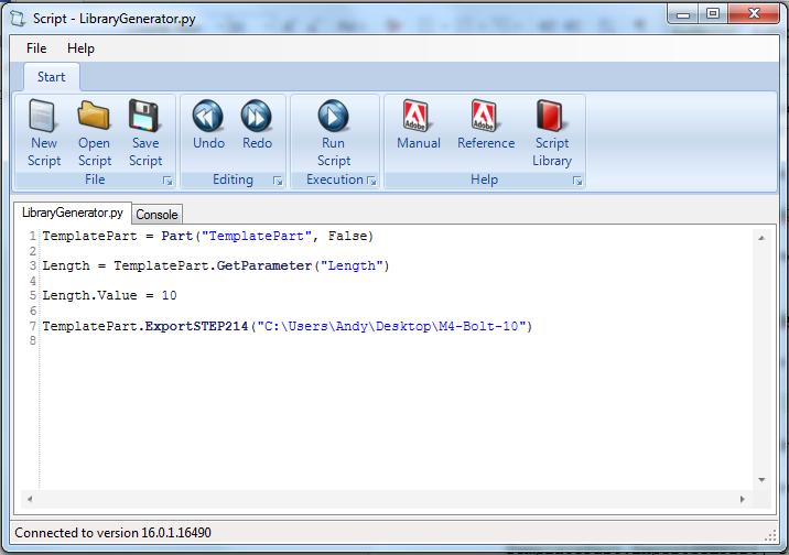
TemplatePart = Part(“TemplatePart”, False)
Next we need to get access to the length parameter that we have already created it. Once we have access to it we can change its value
Length = TemplatePart.GetParameter("Length")
The default units for a script are millimeters, so if we enter the following:
Length.Value = 10
Then we are setting the length of the bolt to 10mm. Enter this into the script.
Now that we have set the length of the bolt we need to export it in a CAD-neutral formal so it can be shared with others. Here is how to do it:
TemplatePart.ExportSTEP214("C:\Users\Andy\Desktop\M4-Bolt-10")
This is what you should have so far:
Save the script and click on the Run button. If there are any errors correct them in the script and try again. If the script is successful you should now have a M4-Bolt-10.stp file.
Generating Multiple Parts
So far it’s not very interesting. We’ve generated a single STEP part that we could have easily created directly in Geomagic Design without needing scripting. Now we will look at generating multiple parts in one go.
The first step is to create a function that is given a length and creates a STEP file. A function is a way of grouping parts of a script together so they can be run over and over again. Edit your script to look like the following:
def GenerateBolt(NewLength):
  Length.Value = NewLength
  TemplatePart.ExportSTEP214("C:\Users\Andy\Desktop\M4-Bolt-"+str(NewLength))

TemplatePart = Part("TemplatePart", False)

Length = TemplatePart.GetParameter("Length")

GenerateBolt(10)
GenerateBolt(12)
We now have a function called GenerateBolt that takes a length and creates a STEP file. The function has to be defined before it is used so put it at the start of the script.
Another key change is that the name of the STEP file contains the length, whatever that may be. This is achieved by appending “M4-Bolt-“ with the length value.
Run the script. It will call GenerateBolt twice and create two STEP files containing a 10mm bolt and a 12mm bolt.
The final step is to create a loop that goes from a minimum length to a maximum length creating bolts. Replace the two calls to GenerateBolt with the following:
MinimumLength = 10
MaximumLength = 20
for NewLength in range(MinimumLength, MaximumLength + 1):
  GenerateBolt(NewLength)
Run the script and it will generate bolts with lengths from 10mm to 20mm.
Here is the final script with comments added to explain:
# Takes a template bolt and creates a library of bolts of different lengths in
# a CAD neutral format

# Creates a bolt of a specific length. NewLength = desired length of bolt in mm
# Saves the bolt to the desktop as a STEP file
def GenerateBolt(NewLength):
  Length.Value = NewLength
  TemplatePart.ExportSTEP214("C:\Users\Andy\Desktop\M4-Bolt-" + str(NewLength))

# Get access to currently opened part that we will used as a template
TemplatePart = Part("TemplatePart", False)

# The template part has a Length parameter defined which we will control
Length = TemplatePart.GetParameter("Length")

# Create bolts from 10mm to 20mm
MinimumLength = 10
MaximumLength = 20
for NewLength in range(MinimumLength, MaximumLength + 1):
  GenerateBolt(NewLength)

Rendering 3D Models
Jun 23rd
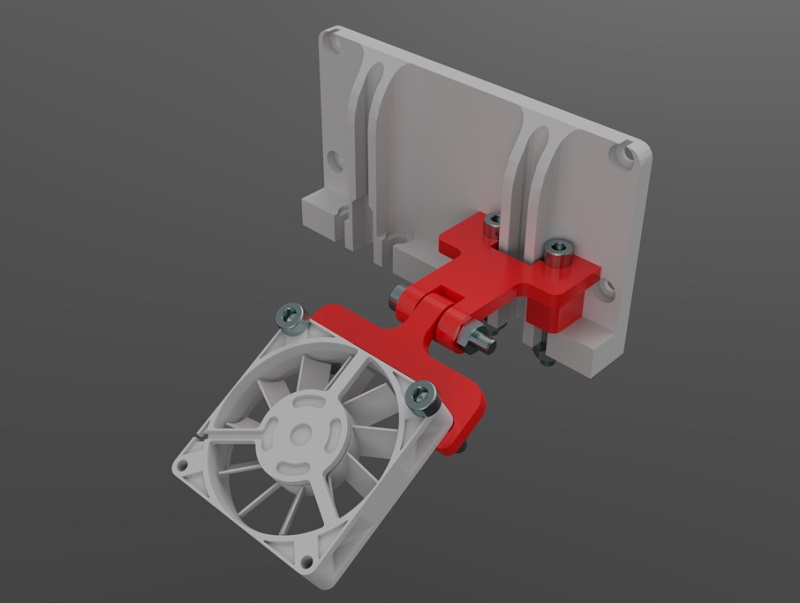
Rendering models using a variety of materials allows a finished object to be viewed and analyzed before committing to cutting wood or printing plastic. SimLab Composer works very well with Alibre Design. Here is an example showing my fan mount for the current RepRapPro Mendel design:
The nozzle mount is an STL from RepRapPro. The fan is an IGES file from GrabCAD. The M3 nuts and bolts are STLs from TraceParts. Finally the fan mount was exported as 3D PDF from Alibre Design.

Scripting Metric Screws in Alibre Design
Apr 10th
Creating screws is tedious. There are lots of diameter and length combinations and there is more to a screw than first meets the eye. Creating a parts library containing lots of variations is a perfect use for ADScript.
Here is a M3 x 20mm socket cap screw generated from the script below.
This screw is modeled to the ISO 4762 standard. Notice the threads are missing? Modeling the threads is generally a waste of time and resources as the aim is to ensure a screw fits, is long enough and there is enough clearance to install it.
# Creates a metric socket cap screw using ISO 4762
# See: http://practicalmaintenance.wordpress.com/2009/01/30/socket-head-cap-screws-article-13/

# Size of screw
Diameter = 3.0
Length = 20.0

# Measurements table containing H, F, E, T, C from web page
MetricData = {}
MetricData[1.6]  = [3.14,  2.0,  1.73,  0.7,  0.16]
MetricData[2.0]  = [3.98,  2.6,  1.73,  1.0,  0.2]
MetricData[2.5]  = [4.68,  3.1,  2.3,   1.1,  0.25]
MetricData[3.0]  = [5.68,  3.6,  2.87,  1.3,  0.3]
MetricData[4.0]  = [7.22,  4.7,  3.44,  2.0,  0.4]
MetricData[5.0]  = [8.72,  5.7,  4.58,  2.5,  0.5]
MetricData[6.0]  = [10.22, 6.8,  5.72,  3.0,  0.6]
MetricData[8.0]  = [13.27, 9.2,  6.86,  4.0,  0.8]
MetricData[10.0] = [16.27, 11.2, 9.15,  5.0,  1.0]
MetricData[12.0] = [18.27, 13.7, 11.43, 6.0,  1.2]
MetricData[16.0] = [24.33, 17.7, 16.0,  8.0,  1.6]
MetricData[20.0] = [30.33, 22.4, 19.44, 10.0, 2.0]
MetricData[24.0] = [36.39, 26.4, 21.73, 12.0, 2.4]
MetricData[30.0] = [45.39, 33.4, 25.15, 15.5, 3.0]
MetricData[36.0] = [54.46, 39.4, 30.85, 19.0, 3.6]
MetricData[42.0] = [63.46, 45.6, 36.57, 24.0, 4.2]
MetricData[48.0] = [72.46, 52.6, 41.13, 28.0, 4.8]
MetricData[56.0] = [84.54, 63.0, 46.83, 34.0, 5.6]
MetricData[64.0] = [96.54, 71.0, 52.53, 38.0, 6.4]

CapDiameter = MetricData[Diameter][0]
FilletTransitionDiameter = MetricData[Diameter][1]
HexHoleDiameter = MetricData[Diameter][2]
HexHoleDepth = MetricData[Diameter][3]
RimFilletRadius = MetricData[Diameter][4]

# all values are in millimeters
Units.Current = UnitTypes.Millimeters

# Create part
Screw = Part("Cap Screw M%dx%d" % (Diameter, Length))

# body
Profile = Screw.AddSketch("Profile", Screw.GetPlane("XY-Plane"))
Profile.AddLines([0, 0, 0, CapDiameter / 2, Diameter, CapDiameter / 2, Diameter, Diameter / 2, Diameter + Length, Diameter / 2, Diameter + Length, 0, 0, 0], False)
Screw.AddRevolveBoss("Body", Profile, Screw.GetAxis("X-Axis"), 360)

# hex hole
HexHole = Screw.AddSketch("Hole", Screw.GetFace("Face<5>"))
HexHole.AddPolygon(0, 0, HexHoleDiameter, 6, False)
Screw.AddExtrudeCut("Hex Hole", HexHole, HexHoleDepth + ((FilletTransitionDiameter - Diameter) / 2.0), True)

# fillet from cap to shaft
Screw.AddFillet("Cap Joint", Screw.GetEdge("Edge<21>"), (FilletTransitionDiameter - Diameter) / 2.0, False)
# fillet at bottom of hex hole
Screw.AddFillet("Hex Hole Bottom", [Screw.GetEdge("Edge<5>"), Screw.GetEdge("Edge<9>"), Screw.GetEdge("Edge<12>"), Screw.GetEdge("Edge<21>"), Screw.GetEdge("Edge<18>"), Screw.GetEdge("Edge<15>")], (FilletTransitionDiameter - Diameter) / 2.0, False)
# fillet on rim
Screw.AddFillet("Cap Rim", Screw.GetEdge("Edge<35>"), RimFilletRadius, False)

Using Alibre Design for 3D Printing of Multi-Part Projects
Mar 13th
The easiest way to design projects that involve multiple parts in Alibre Design is to create and edit parts inside an assembly workspace. This allows the edges and cross-sections of one part to be reused in another part which is very useful.
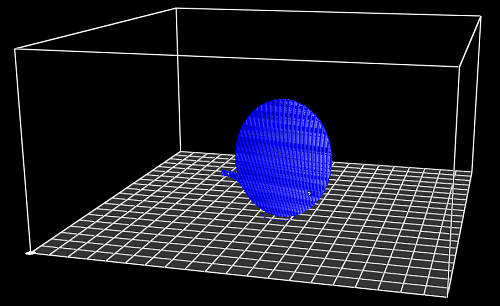
However for 3D printing there is a downside – creating a part inside an assembly results in that part being orientated the same way in the part workspace as it in the assembly workspace. For 3D printing we want a specific side face down on the XY plane. That choice of side depends on the part.
So we have taken advantage of the tools and features that Alibre Design offers but we now have parts that are not orientated correctly for printing. They can be rotated in Alibre Design by creating a new assembly just for that part but there must be an easier way.
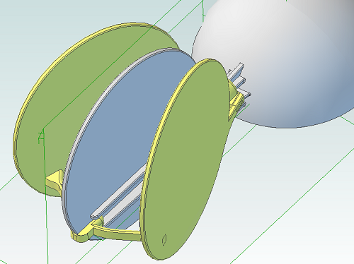
The following screenshot illustrates the problem. The circular panel is in an assembly and orientated the way we need it to check that everything fits together.
Opening the part in it’s own workspace shows the orientation.
Exporting and slicing this part as it is results in the following g-code.
So how can we make this easier, especially if we have an assembly with lots of parts? By using an add-on for Alibre Design.
I’ve updated my AD Assembly Exporter utility that I have previously written about. It can now automatically rotate STLs when they are exported so that the desired face is aligned with the XY plane.
First you must choose the face that will be placed on the print bed.
- Edit the part
- Right-click on the face and choose Insert Plane..
.
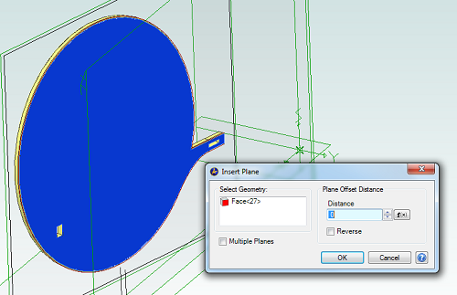
- Click on OK
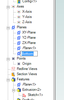
- In the Design Explorer right-click on the new plane and choose Rename
- Enter the name “Bottom”
Now save the part and open the assembly containing it, if it wasn’t already open. Repeat this for all parts in the assembly that will be printed.
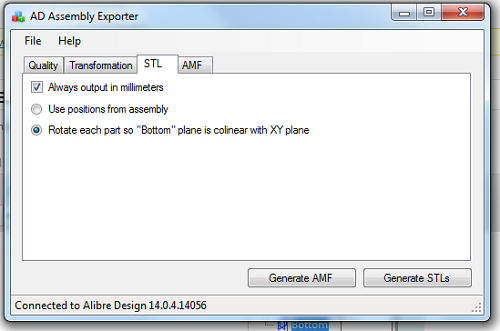
Run AD Assembly Exporter, click on the STL tab and choose the option to rotate using the “Bottom” plane.
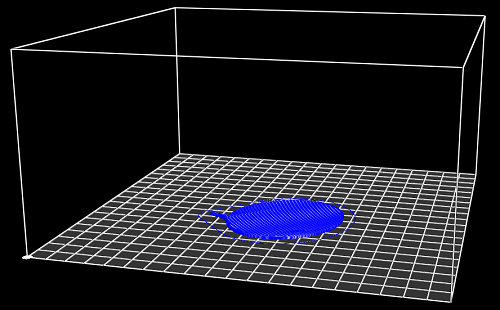
Then click on Generate STLs. Here is the new g-code output:

Using Alibre Design for Multi-color and Multi-material 3D Printing Part II
Feb 27th
Previously I wrote about my little utility that allows exporting properly positioned STLs from Alibre Design so they can be imported into a slicing program for multi-color printing. This is fine for use with the RepRapPro slicer but perhaps not with other slicers.
Slic3r is a very popular, fast and flexible slicing program and now it also supports printing multi-color objects. The file format chosen by it’s author is AMF – Additive Manufacturing File. It is essentially a way to group STL files together into a single object and specify different colors or materials for various parts.
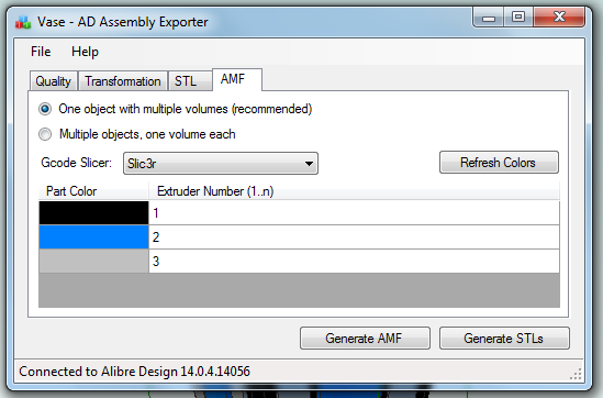
I’ve now updated my exporter utility to support saving Alibre Design assemblies directly to this format:
When an assembly is opened the application obtains the colors used by the parts in the assembly. It is then possible to assign the colors to extruders on the 3D printer. For example in this image black is the body of the object and has been assigned to the primary extruder. It’s necessary to choose which slicing program is being used as there isn’t a standard way of mapping colors to extruders. In particular Slic3r currently has several limitations so by choosing Slic3r the application will stop you from making invalid choices.
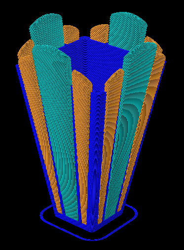
Once generated the AMF file can be loaded directly into Slic3r and sliced. Here is the g-code output shown in Repeiter-Host:
Note that the colors don’t match the Alibre Design assembly because Repetier-Host uses it’s own coloring scheme to represent the different extruders. For example blue is always the first extruder.
Now the object is ready to be printed. The estimated print time for this example is five hours and 45 minutes.

Ray Tracing (Rendering) with Alibre Design PE
Feb 15th
The Professional and Expert versions of Alibre Design come with a ray tracer called Keyshot but the Personal Edition of Alibre Design does not. However it is easily possible to use the free and very powerful Blender to generate ray traces of your 3D models.
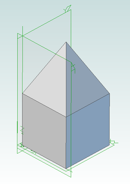
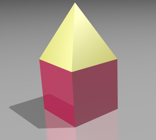
First you must design the parts in Alibre Design and put them together into an assembly. For example here is an assembly showing a pyramid stacked on top of a cube.
Now use my free utility AD Assembly Exporter to export the assembly as a set of STL files. You can download the utility from here. More details on using it can be found in my previous post on 3D printing with Alibre Design.
Next install and run Blender.
Press Delete to delete the default cube. Then go to File -> Import -> STL and choose the STL files that were generated. They will appear in the view in the same positions as they were in the assembly in Alibre Design.
Optionally you can select all the STLs and press ‘S’ to scale them down as they may be a bit large. Now you can assign materials, add lights, position the camera, etc. to render the scene.

Using Alibre Design for Multi-color and Multi-material 3D Printing
Feb 14th
When you wish to print out a part on a 3D printer the workflow is simple – design the part, export to STL and print it. This is fine when you are only printing with a single material or color. Becoming increasingly popular and affordable are 3D printers that support printing with two or three colors/materials at once, such as the Prusa Mendel from RepRapPro. How can Alibre Design be used for this scenario?
In general the easiest way to allocate different colors/materials to a part is to design that part using multiple smaller pieces. Each piece is assigned a color/material for printing. Alibre Design has a very flexible and easy to use way of grouping parts together called an assembly. What we would need therefore is a way of exporting multiple STLs from an assembly preserving their relationships to one another.
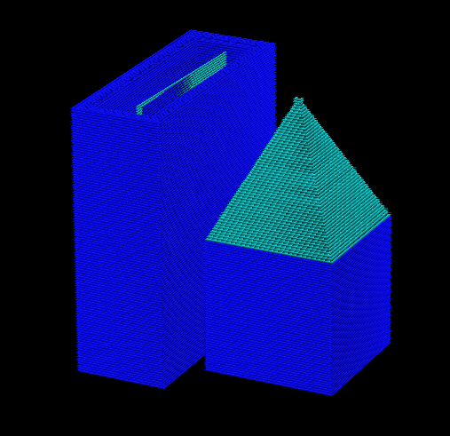
For example, suppose we have a cube and a pyramid and we wanted to place the pyramid on top of the cube and print it in a different color to the cube. We would design the cube and pyramid as two parts then use an assembly to stack the pyramid on top of the cube. Now we need to export the two STLs preserving their position relative to the same origin. This would allow the 3D slicing software to know to stack the pyramid on top of the cube. This is where the problems start.
Alibre Design supports exporting an assembly to a single STL. It merges all the parts together and produces a single object. Information about the individual parts is lost, so this is not usable for our purposes. If you export an individual part or you hide/suppress parts in an assembly then Alibre Design exports the STL using the position and origin in the part file not the assembly, causing the position information to be lost.
An additional problem is the units used in STL files are not defined. If you create a part using centimeters then Alibre Design exports an STL that uses centimeters. Likewise if you create a part using inches then the STL uses inches. The problem is that most, if not all, 3D slicing software assumes the units are millimeters. Solving this for a single part is easy – simply change the units used to millimeters before exporting. However an assembly can be made from multiple parts that all use different units. Regardless of the units chosen for the assembly the STL export will always use the units the part was designed with.
There is one more issue that needs to be addressed. When creating an assembly parts become rotated but the final positions may not be the best for 3D printing. Consider the lid for a box. When creating the assembly it will be rotated so the top is facing upwards but the optimal orientation for printing is probably for the top to be facing downwards onto the build surface. Currently the easiest way to rotate an assembly is to place it into a new assembly as a sub-assembly. This creates an unnecessary extra file and step to perform.
Fortunately Alibre Design has an easy to use API that allows these problems to be solved and I present here my free utility with an exciting name: AD Assembly Exporter.
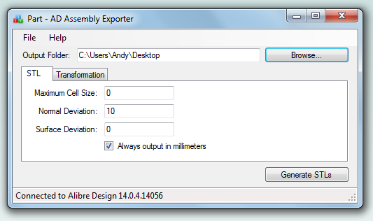
To use start the application and Alibre Design and open an assembly. In the assembly you can optionally hide/suppress parts you do not want to export. The name of the assembly will be shown in the title bar of the AD Assembly Exporter application. Enter the desired settings and click on the Generate STLs button.
The utility supports forcing the units in STLs to millimeters and rotation around an axis. The STL export options match those found in Alibre Design so please see the Alibre Design manual for a description of what they do. Sub-assembly nesting is supported.
Only open one assembly at a time when using the utility. It will export the first assembly found from your open Alibre Design sessions.
Please note that this software is provided “as-is”. More details can be found in the license shown during installation.
Click here to download AD Assembly Exporter (now called WizoPrint)

RepRap Cheap Spool Solution
Sep 16th
Faberdashery supplies very nice 1.75mm PLA however it doesn’t come on a spool. This is annoying. Having to sit at my 3D printer and constantly untangle filament is not my idea of fun so I desperately needed a spool solution. The default response from RepRappers seems to be “print one” so I worked on a design. The total cost of the plastic was a staggering £11.30. That is a crazy price, especially considering I wanted several spools. Also printing out a spool would take hours of having to sit and untangle filament.
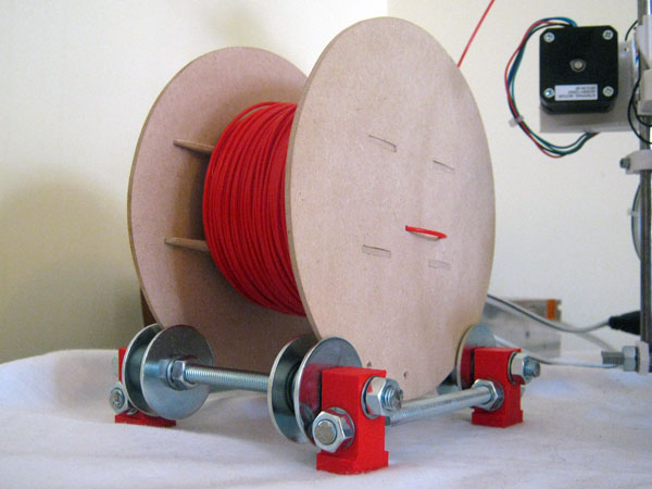
After a couple of hours with a scrollsaw (fretsaw) and some 3mm MDF I had a spool that cost about £1.
The next problem was to create a spool holder. These can be found on Thingiverse in different types and styles however the cleverest (and ones with the least amount of plastic) involved sitting the spool on four bearings. This is a great idea because the spool holder can be easily resized for different spool sizes and trivially scaled to hold multiple spools at the same time.
Spool (files on Thingiverse)
Cut out two of the plates and two of the ends. If your wood is thicker than 3mm then increase the width of the holes in the ends and the length of the tabs on the plates to match.
Drill two 2.5mm holes near the center of one of the ends to hold the start of the filament. Drill some 2.5mm holes near the outside edge to hold the end of the filament when storing it.
Glue the parts together to make the spool. The diameter is 160mm and the width is 90mm. It easily holds 100m of 1.75mm PLA and should hold 300m.
Holder (files on Thingiverse)
Print out four of the foot parts. Cut some M8 threaded rod into four 150mm lengths.
Assemble the two crossbeams as follows (all parts are M8):
nut, lock washer, plastic part, lock washer, mudguard washer, washer, 608ZZ bearing, washer, mudguard washer, lock washer, nut, nut, lock washer, mudguard washer, washer, 608ZZ bearing, washer, mudguard washer, lock washer, plastic part, lock washer, nut
Assemble the two front-back beams as follows:
nut, lock washer, plastic part, lock washer, nut, nut, lock washer, plastic part, lock washer, nut
