Interesting Tech Projects
Posts tagged blender

Ray Tracing (Rendering) with Alibre Design PE
Feb 15th
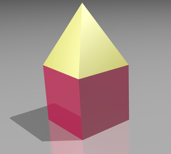
The Professional and Expert versions of Alibre Design come with a ray tracer called Keyshot but the Personal Edition of Alibre Design does not. However it is easily possible to use the free and very powerful Blender to generate ray traces of your 3D models.
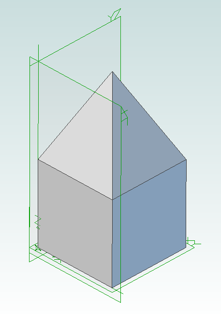
First you must design the parts in Alibre Design and put them together into an assembly. For example here is an assembly showing a pyramid stacked on top of a cube.
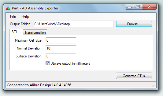
Now use my free utility AD Assembly Exporter to export the assembly as a set of STL files. You can download the utility from here. More details on using it can be found in my previous post on 3D printing with Alibre Design.
Next install and run Blender.
Press Delete to delete the default cube. Then go to File -> Import -> STL and choose the STL files that were generated. They will appear in the view in the same positions as they were in the assembly in Alibre Design.
Optionally you can select all the STLs and press ‘S’ to scale them down as they may be a bit large. Now you can assign materials, add lights, position the camera, etc. to render the scene.

Configuring Blender for CAD
Jul 1st
Blender is a powerful, flexible and free 3D design tool. Initially it appears to be lacking the tools for CAD however with some configuration it’s possible to use precise positioning and rotation along with measuring distances. This article is written for Blender 2.63. Keyboard shortcuts are in parentheses. If you are brand new to Blender I highly recommend the series of tutorials by cgboorman on YouTube and this article assumes you have gone through his tutorials one to six which introduce the basics of Blender.
Start blender and choose View -> Top (numpad 7) and View -> Ortho (numpad 5).
Choose View -> Properties (N) to open the properties panel.
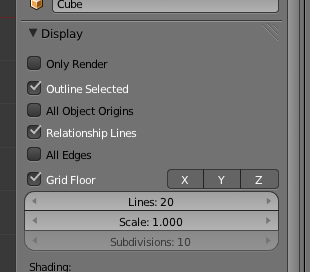
Expand the Display section. Click on “Z” to show the Z-axis and increase the number of grid lines from 16 to increase the size of the grid.
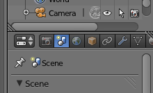
In the Properties window (not the properties panel) – which is by default shown on the right – click on the Scene tab.
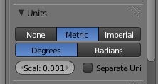
Under Units click on Metric and for the scale enter “0.001”.
Choose File -> User Preferences and click on Addons.
Click on 3D View on the left then expand the 3D View: Measure Panel item.
Check the checkbox at the top right to enable the measure panel addon then close the preferences.
Close the timeline window by merging the 3D View with the timeline.
In the information bar at the top create a new screen layout by clicking on the + and enter the name CAD.
Choose File -> Save User Settings.
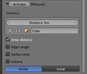
Back in the properties panel (N) scroll down to the bottom and a new section called Measure has been added. Click on the Activate button and expand the section.
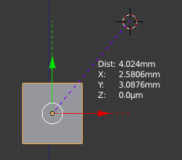
At this point the measurement from the origin of the current object to the 3D cursor is shown. These measurements are updated as you move the 3D cursor and when you move the selected object.
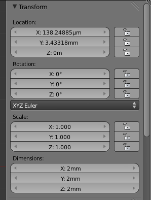
In the properties panel (N) it is now possible to precisely position an object by directly entering the X, Y and Z values in metric units. For example you can enter “2mm”, “4.2cm” or “6.33m”. It is also possible to set the dimensions in metric units and the rotation in degrees. The position of the 3D cursor can be precisely set in metric units as well.
When you restart blender this CAD-friendly configuration will be restored. The measure tool has to be activated each time but that is just a case of scrolling down to the bottom of the properties panel and clicking on the Activate button.
Having measurements for a cube based on the center is not too user friendly for CAD. It can be moved to a corner with the following steps:
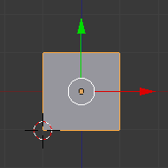
Assuming you have the default cube which is 2mm in size and the location of the cube is 0mm, 0mm, 0mm, open the properties panel (N) and move the 3D cursor to -1mm, -1mm, -1mm. This puts the 3D cursor on the bottom left vertex of the cube.
Choose Object -> Transform -> Origin to 3D Cursor
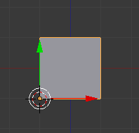
The small dot that denotes the object origin will move to the vertex. The properties panel (N) will now show the location of the cube to be -1mm, -1mm, -1mm.
Finally grid snapping can be turned on by clicking on the magnet icon at the bottom of the 3D view.
![]() Once enabled moving or resizing an object will snap it to the 1mm grid.
Once enabled moving or resizing an object will snap it to the 1mm grid.
View an excellent series of tutorials on using Blender for CAD (although it is the 2.4 series).
