Interesting Tech Projects
Posts tagged alibre

Rendering 3D Models
Jun 23rd
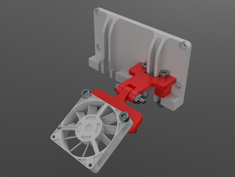
Rendering models using a variety of materials allows a finished object to be viewed and analyzed before committing to cutting wood or printing plastic. SimLab Composer works very well with Alibre Design. Here is an example showing my fan mount for the current RepRapPro Mendel design:
The nozzle mount is an STL from RepRapPro. The fan is an IGES file from GrabCAD. The M3 nuts and bolts are STLs from TraceParts. Finally the fan mount was exported as 3D PDF from Alibre Design.

Involute Gears in Alibre Design
Apr 25th
The most common type of gear is the involute gear, which provides smooth and efficient operation. A gear is defined by the following parameters:
- Pitch diameter (diameter of gear)
- Diametral pitch (tooth size)
- Number of teeth
- Pressure angle (commonly 14.5, 20 or 25 degrees)
The pressure angle defines the shape of a tooth. For two gears to mesh the pressure angle and diametral pitch must be the same (i.e. the shape and size of the teeth must match). There is a simple relationship between pitch diameter, diametral pitch and number of teeth so when defining a gear we only need to specify two of those parameters.
The ability to create involute gears is included in python-based ADScript. Let’s see how.
NumberofTeeth = 20
PitchDiameter = 30
PressureAngle = 20

InputGear = Part("Input Gear")
XYPlane = InputGear.GetPlane("XY-Plane")
GearSketch = InputGear.AddGearNP("Gear Profile", NumberofTeeth, PitchDiameter, PressureAngle, 0, 0, XYPlane)
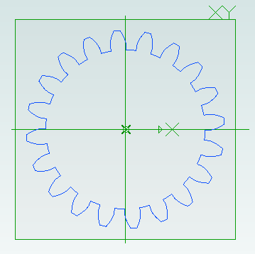
This script creates a new part called Input Gear and then adds a sketch to it on the XY-plane for the profile of a gear by calling AddGearNP. NP shows which two parameters are used, N = number of teeth and P = pitch diameter.
The 0, 0 defines the coordinates of the center of the gear.
Once the gear has been created we can read out the diametral pitch:
DiametralPitch = GearSketch.DiametralPitch
There are two other functions that we can call to create gears, depending on which two parameters we wish to use.
GearSketch1 = MyPart.AddGearDN("Gear Profile", DiametralPitch, NumberofTeeth, PressureAngle, 0, 0, XYPlane)
PitchDiameter = GearSketch1.PitchDiameter

GearSketch2 = MyPart.AddGearDP("Gear Profile", DiametralPitch, PitchDiameter, PressureAngle, 0, 0, XYPlane)
NumberofTeeth = GearSketch2.NumberofTeeth
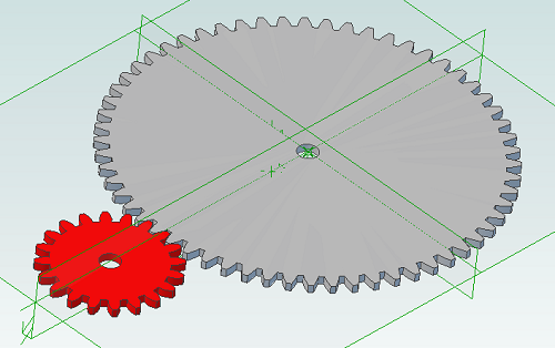
Here is an example script that shows how we can create two gears that can be used together to provide a 3:1 reduction ratio:
# all values are in millimeters
Units.Current = UnitTypes.Millimeters

# pressure angle has to be the same for both gears
# common values are 14.5, 20 and 25
# larger pressure angle = stronger teeth
PressureAngle = 20

# thickness of gears
Thickness = 2
# shaft diameter
ShaftDiameter = 5

# define input gear - 20 teeth and 30mm pitch diameter
Gear1Teeth = 20
Gear1Diameter = 30

# create input gear using number of teeth and pitch diameter
Gear1Part = Part("Input Gear")
Gear1 = Gear1Part.AddGearNP("Gear Profile", Gear1Teeth, Gear1Diameter, PressureAngle, 0, 0, Gear1Part.GetPlane("XY-Plane"))
Gear1.AddCircle(0, 0, ShaftDiameter, False)
Gear1Part.AddExtrudeBoss("Gear", Gear1, Thickness, False)

# diametral pitch must be the same for both gears as this defines tooth size
# use diametral pitch for output gear from input gear calculated value
Gear2DiametralPitch = Gear1.DiametralPitch

# we want a ratio of 1:3 so output gear has three times the number of teeth
Gear2Teeth = Gear1Teeth * 3

# create output gear using number of teeth and diametral pitch
Gear2Part = Part("Output Gear")
Gear2 = Gear2Part.AddGearDN("Gear Profile", Gear2DiametralPitch, Gear2Teeth, PressureAngle, 0, 0, Gear2Part.GetPlane("XY-Plane"))
Gear2.AddCircle(0, 0, ShaftDiameter, False)
Gear2Part.AddExtrudeBoss("Gear", Gear2, Thickness, False)

# get the calculated pitch diameter of the output gear
Gear2Diameter = Gear2.PitchDiameter

# calculate distance between gear centers so we know how far apart the shafts need to be
print "Distance between gear centers = %fmm\n" % ((Gear1Diameter + Gear2Diameter) / 2)
And the result:


