Interesting Tech Projects
Windows

Using Alibre Design for Multi-color and Multi-material 3D Printing Part II
Feb 27th
Previously I wrote about my little utility that allows exporting properly positioned STLs from Alibre Design so they can be imported into a slicing program for multi-color printing. This is fine for use with the RepRapPro slicer but perhaps not with other slicers.
Slic3r is a very popular, fast and flexible slicing program and now it also supports printing multi-color objects. The file format chosen by it’s author is AMF – Additive Manufacturing File. It is essentially a way to group STL files together into a single object and specify different colors or materials for various parts.
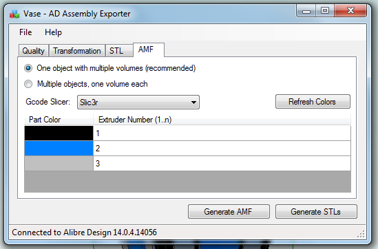
I’ve now updated my exporter utility to support saving Alibre Design assemblies directly to this format:
When an assembly is opened the application obtains the colors used by the parts in the assembly. It is then possible to assign the colors to extruders on the 3D printer. For example in this image black is the body of the object and has been assigned to the primary extruder. It’s necessary to choose which slicing program is being used as there isn’t a standard way of mapping colors to extruders. In particular Slic3r currently has several limitations so by choosing Slic3r the application will stop you from making invalid choices.
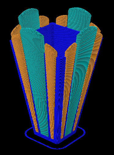
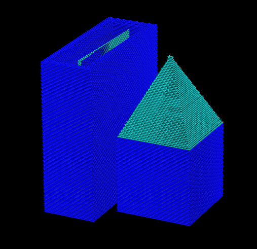
Once generated the AMF file can be loaded directly into Slic3r and sliced. Here is the g-code output shown in Repeiter-Host:
Note that the colors don’t match the Alibre Design assembly because Repetier-Host uses it’s own coloring scheme to represent the different extruders. For example blue is always the first extruder.
Now the object is ready to be printed. The estimated print time for this example is five hours and 45 minutes.

Ray Tracing (Rendering) with Alibre Design PE
Feb 15th
The Professional and Expert versions of Alibre Design come with a ray tracer called Keyshot but the Personal Edition of Alibre Design does not. However it is easily possible to use the free and very powerful Blender to generate ray traces of your 3D models.
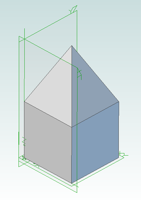
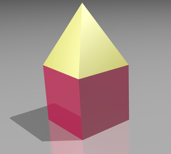
First you must design the parts in Alibre Design and put them together into an assembly. For example here is an assembly showing a pyramid stacked on top of a cube.
Now use my free utility AD Assembly Exporter to export the assembly as a set of STL files. You can download the utility from here. More details on using it can be found in my previous post on 3D printing with Alibre Design.
Next install and run Blender.
Press Delete to delete the default cube. Then go to File -> Import -> STL and choose the STL files that were generated. They will appear in the view in the same positions as they were in the assembly in Alibre Design.
Optionally you can select all the STLs and press ‘S’ to scale them down as they may be a bit large. Now you can assign materials, add lights, position the camera, etc. to render the scene.

Using Alibre Design for Multi-color and Multi-material 3D Printing
Feb 14th
When you wish to print out a part on a 3D printer the workflow is simple – design the part, export to STL and print it. This is fine when you are only printing with a single material or color. Becoming increasingly popular and affordable are 3D printers that support printing with two or three colors/materials at once, such as the Prusa Mendel from RepRapPro. How can Alibre Design be used for this scenario?
In general the easiest way to allocate different colors/materials to a part is to design that part using multiple smaller pieces. Each piece is assigned a color/material for printing. Alibre Design has a very flexible and easy to use way of grouping parts together called an assembly. What we would need therefore is a way of exporting multiple STLs from an assembly preserving their relationships to one another.
For example, suppose we have a cube and a pyramid and we wanted to place the pyramid on top of the cube and print it in a different color to the cube. We would design the cube and pyramid as two parts then use an assembly to stack the pyramid on top of the cube. Now we need to export the two STLs preserving their position relative to the same origin. This would allow the 3D slicing software to know to stack the pyramid on top of the cube. This is where the problems start.
Alibre Design supports exporting an assembly to a single STL. It merges all the parts together and produces a single object. Information about the individual parts is lost, so this is not usable for our purposes. If you export an individual part or you hide/suppress parts in an assembly then Alibre Design exports the STL using the position and origin in the part file not the assembly, causing the position information to be lost.
An additional problem is the units used in STL files are not defined. If you create a part using centimeters then Alibre Design exports an STL that uses centimeters. Likewise if you create a part using inches then the STL uses inches. The problem is that most, if not all, 3D slicing software assumes the units are millimeters. Solving this for a single part is easy – simply change the units used to millimeters before exporting. However an assembly can be made from multiple parts that all use different units. Regardless of the units chosen for the assembly the STL export will always use the units the part was designed with.
There is one more issue that needs to be addressed. When creating an assembly parts become rotated but the final positions may not be the best for 3D printing. Consider the lid for a box. When creating the assembly it will be rotated so the top is facing upwards but the optimal orientation for printing is probably for the top to be facing downwards onto the build surface. Currently the easiest way to rotate an assembly is to place it into a new assembly as a sub-assembly. This creates an unnecessary extra file and step to perform.
Fortunately Alibre Design has an easy to use API that allows these problems to be solved and I present here my free utility with an exciting name: AD Assembly Exporter.
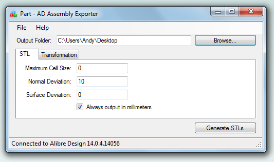
To use start the application and Alibre Design and open an assembly. In the assembly you can optionally hide/suppress parts you do not want to export. The name of the assembly will be shown in the title bar of the AD Assembly Exporter application. Enter the desired settings and click on the Generate STLs button.
The utility supports forcing the units in STLs to millimeters and rotation around an axis. The STL export options match those found in Alibre Design so please see the Alibre Design manual for a description of what they do. Sub-assembly nesting is supported.
Only open one assembly at a time when using the utility. It will export the first assembly found from your open Alibre Design sessions.
Please note that this software is provided “as-is”. More details can be found in the license shown during installation.
Click here to download AD Assembly Exporter (now called WizoPrint)
Using Inkscape for CNC Designs and DXFs
Sep 4th
Update: see this later post before following the instructions below.
I don’t care for most of the DXF editors available. They seem a bit clunky and not too friendly. But I do like Inkscape. Unfortunately it doesn’t export DXF files.
Here is a way of getting Inkscape 0.46 to export DXF files which can then be processed in a CAM program to generate g-code for a CNC machine.
Firstly install Inkscape 0.46. It must be this version.
Next go to this post on BobandEileen.com, right click on the link to “dxf_templates.py” and save it in C:\Program Files\Inkscape\share\extensions.
Next step is to go to another post on BobandEileen.com, right click on the two .py files (“simpletransform.py” and “better_dxf_outlines.py”) and save in the same place. Then do the same for “better_dxf_outlines.inx”.
Restart Inkscape.
Create a drawing and then move it to the bottom left corner of the page. This corner ends up being the origin. If you want your drawing centered on the origin then center it on the corner of the page.
Go to File -> Save As…
From the list of file types in the save dialog window choose “Better DXF Output (*.dxf)” and save the file.
Now open the DXF file in your favourite CAM program, such as CamBam.
Note that you may need to scale the drawing in your CAM program. Even though I had my drawings correctly sized in Inkscape, they seemed to be quite a bit bigger. If anyone knows how to solve that please post a comment.
Windows Based Restore CD for Acronis True Image
Feb 2nd
Recently I needed to restore a backup made with Acronis True Image, however when I booted using the True Image recovery CD it didn’t work. Instead of restoring the image it rebooted the PC. Not very helpful.
After a bit of research it turns out that Acronis uses Linux for their recovery CD and sometimes this has problems with the hardware. An alternative is to use a free tool to create a Windows based recovery CD that runs True Image. The software is called BartPE.
Download BartPE (PE Builder) and install it.
If you have Acronis True Image 10 then you already have the BartPE plugin. If you have Acronis True Image 11 then I believe you have to register your copy and log into the Acronis site for the free download. For True Image 10, go to C:\Program Files\Acronis\TrueImageHome and rename the BartPE folder to “AcronisTrueImage”.
Copy the AcronisTrueImage folder to the “plugin” folder inside the BartPE installation folder. In my case that meant copying it to C:\pebuilder3110a\plugin
Run PE Builder from the Start menu.
Select the location where your Windows installation files are
Click on “Plugins” and make sure that Acronis True Image is enabled (should be by default).
Choose desired media output.
Click on “Build”.
This will either generate an ISO file for burning to a CD or burn the CD for you (depending on the options you choose).
Next, boot your PC with the BartPE CD inserted. Once you have gone through the network options, Acronis True Image can be found on the Go menu at:
Go -> System -> Storage -> Acronis True Image
