Interesting Tech Projects
Software Engineering
Accessing an Overloaded C# Constructor from IronPython
May 14th
The C# class ‘Foo’ has four constructors. The glue between IronPython and C# is not choosing the correct one. Here is how to force it.
import clr
typ = clr.GetClrType(Foo)
ctor = typ.GetConstructors()[3]
newfoo = ctor.Invoke(System.Array[object](['string value', 1234]))
newfoo is now an instance of the Foo object, created using a string and int parameters. Here we are assuming the fourth constructor is the one we want, which isn’t very robust. Instead the constructors can be enumerated and the parameters evaluated to determine the correct constructor to use.

Generating a Part Library in Geomagic Design
Jul 5th
Introduction
This tutorial demonstrates how to create a library of parts in a CAD neutral format based on a single template part. It takes advantage of parameterization in Geomagic Design.
We will start by creating the base part that we will use to create the library. This will be a simple cap head bolt.
Next we will use WizoScript to generate a library of 10 bolts of different lengths.
This type of task is ideally suited to scripting because it handles the tedious repetitive operations needed. While the part demonstrated in this tutorial is simple the same principles can easily be used for complex parts with multiple parameters.
Creating the Template Part
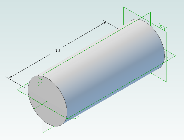
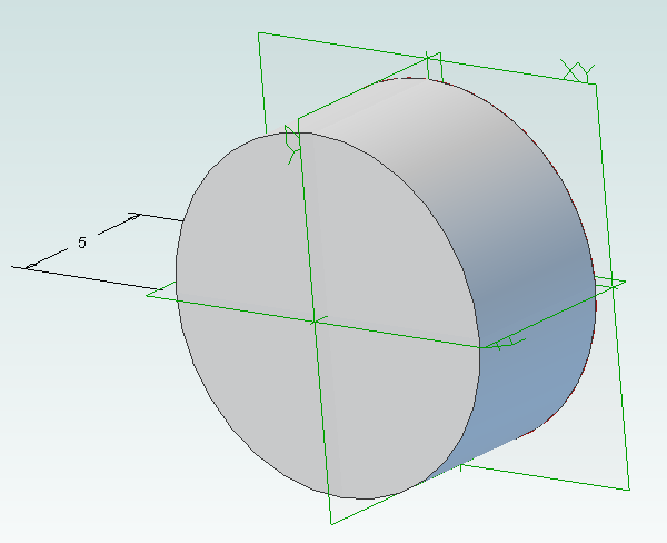
In Geomagic Design create a new part and then a sketch on the XY-Plane. On this sketch draw a circle centered on the origin with a diameter of 4mm and then extrude into a cylinder with a length of 10mm.
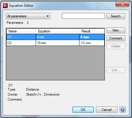
Under the Viewing and Analysis tab click on the Equation Editor button.
Double-click on “D2” and enter “Length” to give the length of the bolt a useful name then close the equation editor window.
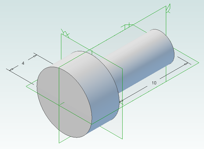
Create the bolt head by adding a sketch to the end of the cylinder on the XY-Plane, setting the diameter to 8mm and extruding 4mm.
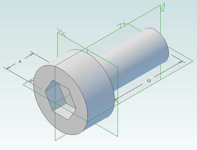
Create a new sketch on the top of the bolt head, draw a hexagon with an inside diameter of 4mm and then extrude cut 2mm.
Create a new folder called “PartLibrary” and save as TemplatePart.AD_PRT. Keep the part open in Geomagic to continue with the tutorial.
Writing a Basic Script
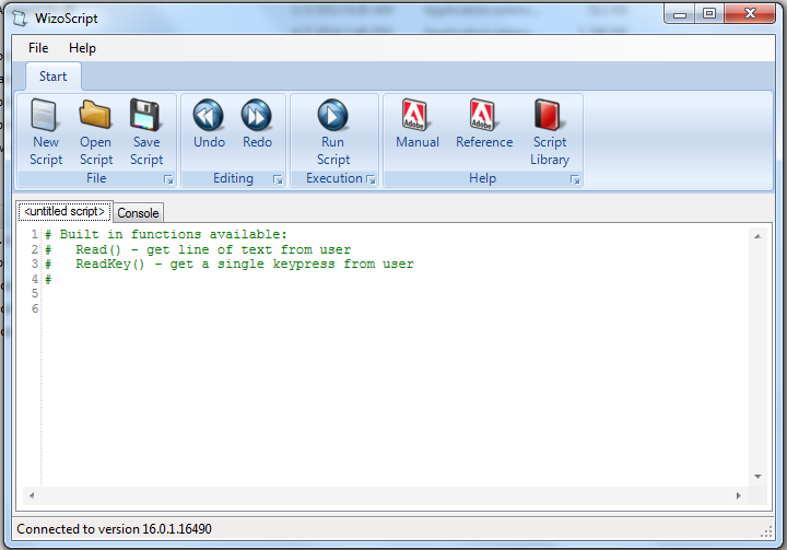
Start WizoScript 1.70 or later. When it runs it automatically creates an empty script that we can start using right away.
First we need to tell the script about our template part. For this tutorial the part must be open in Geomagic when the script runs, however it is possible to use a saved part that is not currently open. Please see the WizoScript reference manual for further details.
The following script line tells WizoScript “I have a part open and I want you to use it”:
TemplatePart = Part(“TemplatePart”, False)
Next we need to get access to the length parameter that we have already created it. Once we have access to it we can change its value
Length = TemplatePart.GetParameter("Length")
The default units for a script are millimeters, so if we enter the following:
Length.Value = 10
Then we are setting the length of the bolt to 10mm. Enter this into the script.
Now that we have set the length of the bolt we need to export it in a CAD-neutral formal so it can be shared with others. Here is how to do it:
TemplatePart.ExportSTEP214("C:\Users\Andy\Desktop\M4-Bolt-10")
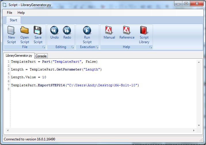
This is what you should have so far:
Save the script and click on the Run button. If there are any errors correct them in the script and try again. If the script is successful you should now have a M4-Bolt-10.stp file.
Generating Multiple Parts
So far it’s not very interesting. We’ve generated a single STEP part that we could have easily created directly in Geomagic Design without needing scripting. Now we will look at generating multiple parts in one go.
The first step is to create a function that is given a length and creates a STEP file. A function is a way of grouping parts of a script together so they can be run over and over again. Edit your script to look like the following:
def GenerateBolt(NewLength):
  Length.Value = NewLength
  TemplatePart.ExportSTEP214("C:\Users\Andy\Desktop\M4-Bolt-"+str(NewLength))

TemplatePart = Part("TemplatePart", False)

Length = TemplatePart.GetParameter("Length")

GenerateBolt(10)
GenerateBolt(12)
We now have a function called GenerateBolt that takes a length and creates a STEP file. The function has to be defined before it is used so put it at the start of the script.
Another key change is that the name of the STEP file contains the length, whatever that may be. This is achieved by appending “M4-Bolt-“ with the length value.
Run the script. It will call GenerateBolt twice and create two STEP files containing a 10mm bolt and a 12mm bolt.
The final step is to create a loop that goes from a minimum length to a maximum length creating bolts. Replace the two calls to GenerateBolt with the following:
MinimumLength = 10
MaximumLength = 20
for NewLength in range(MinimumLength, MaximumLength + 1):
  GenerateBolt(NewLength)
Run the script and it will generate bolts with lengths from 10mm to 20mm.
Here is the final script with comments added to explain:
# Takes a template bolt and creates a library of bolts of different lengths in
# a CAD neutral format

# Creates a bolt of a specific length. NewLength = desired length of bolt in mm
# Saves the bolt to the desktop as a STEP file
def GenerateBolt(NewLength):
  Length.Value = NewLength
  TemplatePart.ExportSTEP214("C:\Users\Andy\Desktop\M4-Bolt-" + str(NewLength))

# Get access to currently opened part that we will used as a template
TemplatePart = Part("TemplatePart", False)

# The template part has a Length parameter defined which we will control
Length = TemplatePart.GetParameter("Length")

# Create bolts from 10mm to 20mm
MinimumLength = 10
MaximumLength = 20
for NewLength in range(MinimumLength, MaximumLength + 1):
  GenerateBolt(NewLength)

Cooke Triplet Lens System in Geomagic Design
Jul 3rd
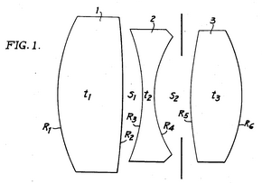
The Cooke Triplet is a system of three lenses designed in the 19th century to reduce distortion. In 1950 a specific triplet was invented and patented by Eastman Kodak (EF=100mm, f/1.9) and we will look at how to recreate it in Geomagic Design using scripting. We will create a script that can generate any type of thick lens, including how to solve the lensmaker’s equation. Hopefully the techniques demonstrated here will be useful to others solving and creating mathematical shapes in Geomagic Design.
Download, install and run WizoScript 1.70 or later. Start Geomagic Design. This script was tested with version 16.0.1.16490.
First we must enable a couple of useful libraries and make sure our script is using millimeters to match the values in the patent.
import sympy
from sympy import *
import math

Units.Current = UnitTypes.Millimeters
We are going to generate three lens parts and save them so we need to specify a location to save to. Change this to make your PC.
OutputFolder = "P:\\temp"
The patent completely describes the three lenses but we are going to make it a bit more interesting by calculating the radius of the back of the lens from the focal length. To do that we need to use the lensmaker’s equation.
In the formula the radius of the back of the lens is R2. This appears in two locations in the formula. We could rearrange it to give us R2 = … but that is a bit tedious. Instead we can leave WizoScript to worry about it instead. Here is how we enter the equation into the script using ‘rb’ to represent the radius of the back of the lens.
# calculates the back radius of a lens based on the other parameters
# uses the lensmaker's equation
def GetBackRadius(FrontRadius, Thickness, RefractiveIndex, FocalLength):
  rb = Symbol('rb')
  Equation = Eq((RefractiveIndex-1)*((1/FrontRadius)-(1/rb)+(((RefractiveIndex-1)*Thickness)/(RefractiveIndex*FrontRadius*rb))),(1/FocalLength))
  # we don't bother rearranging the equation, instead we let the sympy module do that for us
  BackRadius = solve(Equation)[0]
  return BackRadius
WizoScript rearranges the equation and calculates the value we need using the single line:
BackRadius = solve(Equation)[0]
The equation is placed into a function called ‘GetBackRadius’ which calculates the value when given a set of parameters, such as the thickness of the lens, refractive index of the material, etc. We can call the function repeatedly for different parameters.
Now we need to start creating a part for a single lens. First we tell Geomagic Design to create a part. We are going to do that in a new function.
# creates a part representing a lens based on a set of parameters
def GenerateLens(Name, Folder, FrontRadius, Thickness, RefractiveIndex, FocalLength, Diameter):
  # get missing parameter
  BackRadius = GetBackRadius(FrontRadius, Thickness, RefractiveIndex, FocalLength)

  # check diameter is small enough
  if Diameter > abs(FrontRadius):
    print "%s diameter is larger than the front radius %f" % (Name, FrontRadius)
    return
  if Diameter > abs(BackRadius):
    print "%s diameter is larger than the back radius %f" % (Name, BackRadius)
    return

  # create new part
  Lens = Part(Name)
The general approach we will take is to draw a 2D profile of half of the lens on the XY plane and then create a revolve boss around the X axis. The X axis is the optical axis (i.e. the center of rotation for the lens).
  # start creating the 2d sketch representing the shape of the lens
  Profile = Lens.AddSketch("Profile", Lens.GetPlane("XY-Plane"))

  LensRadius = Diameter / 2.0
First we will draw the front of the lens. There are three possibilities, the front is flat (infinite radius), bulging out aka convex (positive radius) or indented aka concave (negative radius). We treat each case individually. Simple trigonometry is used to calculate the end points of the front. Note that infinity is represented in the script by ‘oo’.
  # draw shape of the front of the lens, it can be flat, convex or concave
  if FrontRadius == oo:
    FEndX = 0
    Profile.AddLine(0, 0, FEndX, LensRadius, False)
  elif FrontRadius > 0:
    Angle = asin(LensRadius / FrontRadius)
    FEndX = FrontRadius - (cos(Angle) * FrontRadius)
    Profile.AddArcCenterStartEnd(FrontRadius, 0, FEndX, LensRadius, 0, 0, False)
  else:
    FrontRadius = -FrontRadius
    Angle = asin(LensRadius / FrontRadius)
    FEndX = (cos(Angle) * FrontRadius) - FrontRadius
    Profile.AddArcCenterStartEnd(-FrontRadius, 0, 0, 0, FEndX, LensRadius, False)
The back of the lens is treated in the same way except the sign of the radius is reversed. This means that a convex shape is a negative radius and a concave shape is a positive radius.
  # draw shape of the back of the lens, it can be flat, convex or concave
  if BackRadius == oo:
    BEndX = Thickness
    Profile.AddLine(Thickness, 0, BEndX, LensRadius, False)
  elif BackRadius < 0:
    BackRadius = -BackRadius
    Angle = asin(LensRadius / BackRadius)
    BEndX = (cos(Angle) * BackRadius) - BackRadius + Thickness
    Profile.AddArcCenterStartEnd(Thickness - BackRadius, 0, Thickness, 0, BEndX, LensRadius, False)
  else:
    Angle = asin(LensRadius / BackRadius)
    BEndX = -(cos(Angle) * BackRadius) + BackRadius + Thickness
    Profile.AddArcCenterStartEnd(Thickness + BackRadius, 0, BEndX, LensRadius, Thickness, 0, False)
Before we can add the revolve boss we must make sure the sketch is closed by drawing the line for the outside of the lens and the line along the optical axis
  # check diameter of lens again
  if FEndX > BEndX:
    print "%s diameter is too large" % Name
    return

  # if this is not a "thin" lens then draw top of profile
  if FEndX != BEndX:
    Profile.AddLine(FEndX, LensRadius, BEndX, LensRadius, False)

  # draw line of profile along x axis (optical axis)
  Profile.AddLine(0, 0, Thickness, 0, False)
Now for the revolve boss.
  # create lens by revolving sketch around x axis
  Lens.AddRevolveBoss("Lens", Profile, Lens.GetAxis("X-Axis"), 360.0)
Creating two reference planes for the front and back of the lens will help with aligning them to create the triplet. Finally we save and close the part.
  # add reference planes to aid in aligning this lens with others
  Lens.AddPlane("Front", Lens.GetPlane("YZ-Plane"), 0);
  Lens.AddPlane("Back", Lens.GetPlane("YZ-Plane"), Thickness);

  # save and close
  Lens.Save(Folder)
  Lens.Close()
The last step is to generate the three lenses needed for the triplet using the values from the patent along with the focal length.
# lens 1
GenerateLens("Lens1", OutputFolder, 62.63, 25.56, 1.745, 73.2, 40.0)
# lens 2
GenerateLens("Lens2", OutputFolder, -66.47, 4.51, 1.647, -37.74, 36.0)
# lens 3
GenerateLens("Lens3", OutputFolder, 119.5, 19.92, 1.697, 54.88, 30.0)
The complete script can be obtained from the script library. Running it will generate three part files, one for each lens.
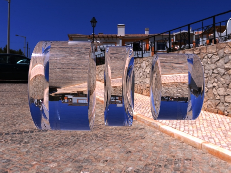
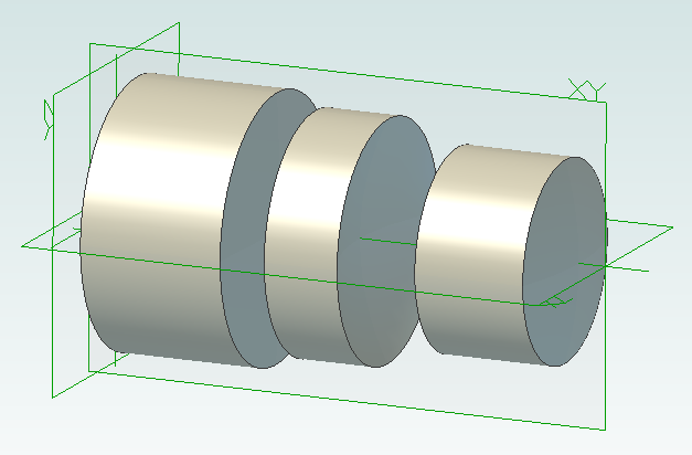
Create a new assembly and add the three lenses in the order lens1, lens2 and lens3. Align the X axis of all three lenses. Align the front plane of lens2 7.89mm from the back plane of lens1. Align the front plane of lens3 14.14mm from the back plane of lens2.

Interactive Mobius Strip Generator for Geomagic Design
Jun 29th
This mini tutorial shows how to generate custom Mobius strips with minimum effort. It demonstrates that python scripting can be used to ask the user for information and then apply it to a part the user is already working on. Hopefully that will be useful to some people when solving problems.
1. Download and install WizoScript 1.70 or later and start it.
2. Start Geomagic Design V16 hotfix 1 (16.0.1.16490) or later.
3. Create a new part and set the units to millimeters.
4. Create a new sketch on the XY plane.
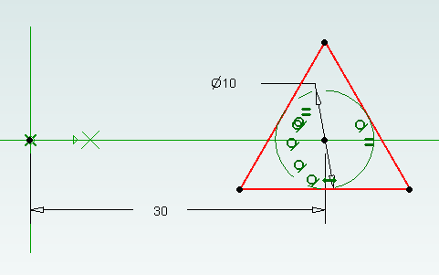
5. Draw a triangle centered on the X axis and set the size of the reference circle to 10mm.
6. Set the center of the triangle 30mm from the origin and exit sketch editing mode.
7. Go to the WizoScript script library and copy the Interactive Mobius Strip Generator. Paste it into WizoScript. Hint: double-clicking on the script in the web-page selects the entire script.
8. Run the script.
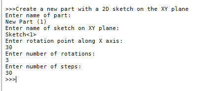
9. You will be asked for the name of the part. Assuming you haven’t saved it enter “New Part (1)”. Then you will be asked for the name of the sketch. Enter “Sketch<1>”.
10. Next you will be asked the rotation point along the X axis. Enter “30”. This puts the rotation point at the center of the triangle.
11. You will be asked for the number of rotations. This is the number of times the mobius strip will completely rotate. Enter “3”.
12. Finally you will be asked to enter the number of steps. Enter “30”.
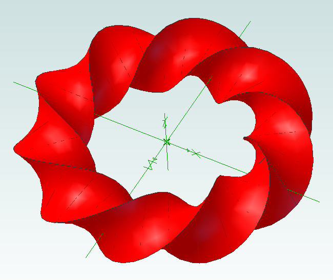
Now the mobius strip will be generated. Be patient as this can take several minutes. Here is what you should have:
Now it’s time to experiment! You can change the shape of the sketch to create different effects. Setting the rotation point closer or further away from the origin will create a “corkscrew” effect. You can increase or decrease the number of rotations. Reducing the number of steps will make the part faster to create but you might have to manually add a guide curve to get a true mobius strip.
Using this script it is possible to run it multiple times on the same part. For example create two sketches, run it on the first sketch and then run it on the second sketch to create two Mobius strips that are intertwined.

WH1080 Weather Station Wind Vane
Jun 10th
I think the jury is still out on the wind vane that comes with WH1080 weather stations (e.g. Fine Offset, Mapin). Some people claim it works fine when placed high up away from any buildings, trees or other obstructions. Many people complain that it is just not reliable regardless. It doesn’t help that the weather stations come with a short pole.
From watching the vane it seems one of the issues is when the wind is gusty. I’ve noticed that when a gust ends the vane becomes destabilized and simply spins around and around.
For me it is simply not feasible to locate the vane on the chimney so I wondered if adding software filtering to my weather station code might work.
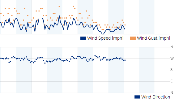
pywws already contains wind direction averaging for hourly summaries so I thought it would give that a try. Here is how the wind direction data looked a few days ago before adding averaging to the code:
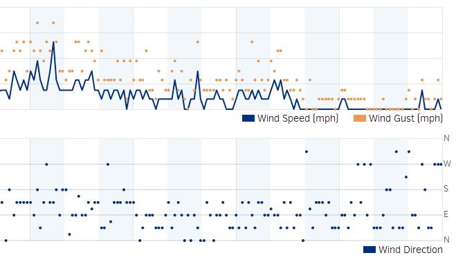 The top part shows the wind speed and gusts. The bottom shows the wind direction. As you can see it is hard to see any pattern beyond the wind coming from the south, east or north.
Here is the wind direction data today after adding the averaging:
Much better. It is clear the wind was coming out of the west. While the above data was being captured I could see the vane swinging from north to south all the time, so it is pretty nice that the averaging was able to pick out the correct wind direction.
As previously mentioned the algorithm was taken from pywws, but with a couple of changes added. It works as follows:
- When the receiver starts it collects a new wind vector every 48 seconds. The vector consists of the wind direction and average speed. This comes directly from the weather station transmitter.
- While the receiver is collecting the first 16 wind vectors it reports the current wind direction to Weather Underground. So for the first 12.8 minutes (16 x 48 seconds) after reset the wind direction is not averaged.
- Once 16 wind vectors have been collected the receiver starts averaging the wind direction and reporting the average to Weather Underground. Every 48 seconds when new data is received the oldest wind vector is overwritten. So the receiver always has the last 16 wind vectors to work with.
- The latest 16 wind vectors are converted into weighted vectors. There is one vector for each compass point direction and the size of each vector is the sum of the average wind speeds measured coming from that direction. This method ensures the result favors directions where stronger winds came from.
- Using some trigonometry the average wind direction is calculated.
- In the situation where there is no wind for all 16 wind vectors (so no wind for 12.8 minutes) then the last average wind direction is used.
The code can be obtained from github.

WH1080 Weather Station and Weather Underground
Jun 7th
A couple of years ago I bought a WH1080 weather station (e.g. Fine Offset, Mapin). It’s available under many brands from many outlets all over the world and is very common. Here are pictures of what this cheap weather station looks like:

I had the touchscreen connected to a Linux sever via USB and used pywws to upload to Weather Underground. This worked well until USB broke so I had to look for a new solution.
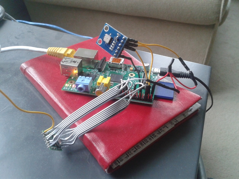
Kevin Sangeelee had developed some code that allowed a Raspberry Pi to receive the 433MHz radio signals and decode them. It also had support for a pressure sensor. Perfect. The code can be found here: http://www.susa.net/wordpress/2012/08/raspberry-pi-reading-wh1081-weather-sensors-using-an-rfm01-and-rfm12b/
The RFM01 was obtained from Maplin for about £4 and was trivially connected to the RPi. Kevin’s article gives the connections. Note: I didn’t use any resistors.
The BMP085 was also easily connected. Purchased from eBay for about £6 it connects directly to the I2C pins. Again, no resistors needed.
The first step was up update Kevin’s code for revision 2 of the RPi. This is required because a GPIO pin has changed and the second I2C bus is now used.
Now I ran into a stumbling block – how to get the data into pywws. I hoped that this problem had already been solved but unfortunately I would have to start writing custom python modules. After thinking about it for a while I decided that all I needed was to upload data to Weather Underground. I didn’t need the other features of pywws. Fortunately Weather Underground has a simple way of uploading using a HTTP GET request. The data just needed to be massaged into the correct format. While I was at it I decided to use the rapid-fire updating. This means that Weather Underground displays new data from your station roughly every 48 seconds – you can watch it continually update.
You can get the code from GitHub here: https://github.com/ajayre/WH1080-Weather-Underground.
Create a text file in the same folder as the executable called wunderground_creds.txt. On the first line enter the name of your weather station ID, for example IWESTYORKS30. On the second line enter your Weather Underground password.
Compile, run and follow Kevin’s instructions for setting up and tuning. Don’t forget to enable the SPI and I2C modules on the RPi. Also make sure you run:
sudo dpkg-reconfigure tzdata
to set the timezone.
Make sure the path to the credentials file in wunderground.c is set correctly. To start the program on boot I used the following in a boot script:
sudo screen -d -m /home/pi/weather/wh1080_rf

Involute Gears in Alibre Design
Apr 25th
The most common type of gear is the involute gear, which provides smooth and efficient operation. A gear is defined by the following parameters:
- Pitch diameter (diameter of gear)
- Diametral pitch (tooth size)
- Number of teeth
- Pressure angle (commonly 14.5, 20 or 25 degrees)
The pressure angle defines the shape of a tooth. For two gears to mesh the pressure angle and diametral pitch must be the same (i.e. the shape and size of the teeth must match). There is a simple relationship between pitch diameter, diametral pitch and number of teeth so when defining a gear we only need to specify two of those parameters.
The ability to create involute gears is included in python-based ADScript. Let’s see how.
NumberofTeeth = 20
PitchDiameter = 30
PressureAngle = 20

InputGear = Part("Input Gear")
XYPlane = InputGear.GetPlane("XY-Plane")
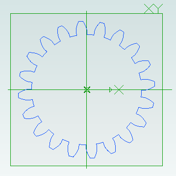
GearSketch = InputGear.AddGearNP("Gear Profile", NumberofTeeth, PitchDiameter, PressureAngle, 0, 0, XYPlane)
This script creates a new part called Input Gear and then adds a sketch to it on the XY-plane for the profile of a gear by calling AddGearNP. NP shows which two parameters are used, N = number of teeth and P = pitch diameter.
The 0, 0 defines the coordinates of the center of the gear.
Once the gear has been created we can read out the diametral pitch:
DiametralPitch = GearSketch.DiametralPitch
There are two other functions that we can call to create gears, depending on which two parameters we wish to use.
GearSketch1 = MyPart.AddGearDN("Gear Profile", DiametralPitch, NumberofTeeth, PressureAngle, 0, 0, XYPlane)
PitchDiameter = GearSketch1.PitchDiameter

GearSketch2 = MyPart.AddGearDP("Gear Profile", DiametralPitch, PitchDiameter, PressureAngle, 0, 0, XYPlane)
NumberofTeeth = GearSketch2.NumberofTeeth
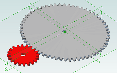
Here is an example script that shows how we can create two gears that can be used together to provide a 3:1 reduction ratio:
# all values are in millimeters
Units.Current = UnitTypes.Millimeters

# pressure angle has to be the same for both gears
# common values are 14.5, 20 and 25
# larger pressure angle = stronger teeth
PressureAngle = 20

# thickness of gears
Thickness = 2
# shaft diameter
ShaftDiameter = 5

# define input gear - 20 teeth and 30mm pitch diameter
Gear1Teeth = 20
Gear1Diameter = 30

# create input gear using number of teeth and pitch diameter
Gear1Part = Part("Input Gear")
Gear1 = Gear1Part.AddGearNP("Gear Profile", Gear1Teeth, Gear1Diameter, PressureAngle, 0, 0, Gear1Part.GetPlane("XY-Plane"))
Gear1.AddCircle(0, 0, ShaftDiameter, False)
Gear1Part.AddExtrudeBoss("Gear", Gear1, Thickness, False)

# diametral pitch must be the same for both gears as this defines tooth size
# use diametral pitch for output gear from input gear calculated value
Gear2DiametralPitch = Gear1.DiametralPitch

# we want a ratio of 1:3 so output gear has three times the number of teeth
Gear2Teeth = Gear1Teeth * 3

# create output gear using number of teeth and diametral pitch
Gear2Part = Part("Output Gear")
Gear2 = Gear2Part.AddGearDN("Gear Profile", Gear2DiametralPitch, Gear2Teeth, PressureAngle, 0, 0, Gear2Part.GetPlane("XY-Plane"))
Gear2.AddCircle(0, 0, ShaftDiameter, False)
Gear2Part.AddExtrudeBoss("Gear", Gear2, Thickness, False)

# get the calculated pitch diameter of the output gear
Gear2Diameter = Gear2.PitchDiameter

# calculate distance between gear centers so we know how far apart the shafts need to be
print "Distance between gear centers = %fmm\n" % ((Gear1Diameter + Gear2Diameter) / 2)
And the result:

Scripting Metric Screws in Alibre Design
Apr 10th
Creating screws is tedious. There are lots of diameter and length combinations and there is more to a screw than first meets the eye. Creating a parts library containing lots of variations is a perfect use for ADScript.
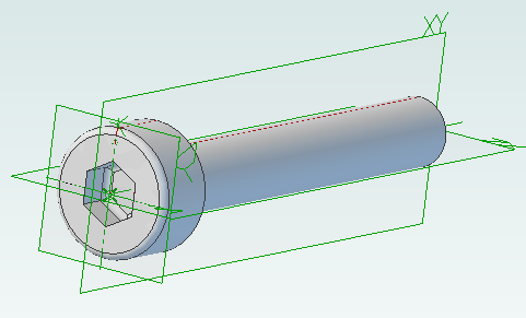
Here is a M3 x 20mm socket cap screw generated from the script below.
This screw is modeled to the ISO 4762 standard. Notice the threads are missing? Modeling the threads is generally a waste of time and resources as the aim is to ensure a screw fits, is long enough and there is enough clearance to install it.
# Creates a metric socket cap screw using ISO 4762
# See: http://practicalmaintenance.wordpress.com/2009/01/30/socket-head-cap-screws-article-13/

# Size of screw
Diameter = 3.0
Length = 20.0

# Measurements table containing H, F, E, T, C from web page
MetricData = {}
MetricData[1.6]  = [3.14,  2.0,  1.73,  0.7,  0.16]
MetricData[2.0]  = [3.98,  2.6,  1.73,  1.0,  0.2]
MetricData[2.5]  = [4.68,  3.1,  2.3,   1.1,  0.25]
MetricData[3.0]  = [5.68,  3.6,  2.87,  1.3,  0.3]
MetricData[4.0]  = [7.22,  4.7,  3.44,  2.0,  0.4]
MetricData[5.0]  = [8.72,  5.7,  4.58,  2.5,  0.5]
MetricData[6.0]  = [10.22, 6.8,  5.72,  3.0,  0.6]
MetricData[8.0]  = [13.27, 9.2,  6.86,  4.0,  0.8]
MetricData[10.0] = [16.27, 11.2, 9.15,  5.0,  1.0]
MetricData[12.0] = [18.27, 13.7, 11.43, 6.0,  1.2]
MetricData[16.0] = [24.33, 17.7, 16.0,  8.0,  1.6]
MetricData[20.0] = [30.33, 22.4, 19.44, 10.0, 2.0]
MetricData[24.0] = [36.39, 26.4, 21.73, 12.0, 2.4]
MetricData[30.0] = [45.39, 33.4, 25.15, 15.5, 3.0]
MetricData[36.0] = [54.46, 39.4, 30.85, 19.0, 3.6]
MetricData[42.0] = [63.46, 45.6, 36.57, 24.0, 4.2]
MetricData[48.0] = [72.46, 52.6, 41.13, 28.0, 4.8]
MetricData[56.0] = [84.54, 63.0, 46.83, 34.0, 5.6]
MetricData[64.0] = [96.54, 71.0, 52.53, 38.0, 6.4]

CapDiameter = MetricData[Diameter][0]
FilletTransitionDiameter = MetricData[Diameter][1]
HexHoleDiameter = MetricData[Diameter][2]
HexHoleDepth = MetricData[Diameter][3]
RimFilletRadius = MetricData[Diameter][4]

# all values are in millimeters
Units.Current = UnitTypes.Millimeters

# Create part
Screw = Part("Cap Screw M%dx%d" % (Diameter, Length))

# body
Profile = Screw.AddSketch("Profile", Screw.GetPlane("XY-Plane"))
Profile.AddLines([0, 0, 0, CapDiameter / 2, Diameter, CapDiameter / 2, Diameter, Diameter / 2, Diameter + Length, Diameter / 2, Diameter + Length, 0, 0, 0], False)
Screw.AddRevolveBoss("Body", Profile, Screw.GetAxis("X-Axis"), 360)

# hex hole
HexHole = Screw.AddSketch("Hole", Screw.GetFace("Face<5>"))
HexHole.AddPolygon(0, 0, HexHoleDiameter, 6, False)
Screw.AddExtrudeCut("Hex Hole", HexHole, HexHoleDepth + ((FilletTransitionDiameter - Diameter) / 2.0), True)

# fillet from cap to shaft
Screw.AddFillet("Cap Joint", Screw.GetEdge("Edge<21>"), (FilletTransitionDiameter - Diameter) / 2.0, False)
# fillet at bottom of hex hole
Screw.AddFillet("Hex Hole Bottom", [Screw.GetEdge("Edge<5>"), Screw.GetEdge("Edge<9>"), Screw.GetEdge("Edge<12>"), Screw.GetEdge("Edge<21>"), Screw.GetEdge("Edge<18>"), Screw.GetEdge("Edge<15>")], (FilletTransitionDiameter - Diameter) / 2.0, False)
# fillet on rim
Screw.AddFillet("Cap Rim", Screw.GetEdge("Edge<35>"), RimFilletRadius, False)

Scripting Polyholes in Alibre Design
Apr 6th
3D printing by using layers of melted plastic filament, such as used by RepRap printers, causes small holes (less than 15mm in diameter) to end up smaller than the designed size. To compensate for this people create designs with larger holes so they shrink to the right size. It’s not an ideal solution – how much do they need to be increased by? What if you later want to send the same design to a commercial printing service that is more accurate?
The RepRap developer Nophead examined this issue and came up with a simple way to design holes that print at the right size regardless of the printing method. He called them polyholes.
In short the solution is to approximate the hole with a polygon and increase it’s size slightly.
Creating these polyholes in a CAD package is tedious. The size has to be calculated and the number of sides varies with the hole size. ADScript has this functionality baked right in. Here is an example python script:
# use millimeters for all values
Units.Current = UnitTypes.Millimeters

# test block dimensions
length = 15
width = 10
depth = 3
# size of test holes
diameter = 3

# create a new part, get the XY plane and create a sketch on the plane
PolyholeTest = Part("PolyholeTest")
XYPlane = PolyholeTest.GetPlane("XY-Plane")
Base = PolyholeTest.AddSketch("Base", XYPlane)

# draw the part outline
Base.AddPolyline([0, 0, length, 0, length, width, 0, width, 0, 0], False)
# draw a regular hole
Base.AddCircle(length / 3, width / 2, diameter, False)
# draw a polyhole
Base.AddPolyhole(length / 3 * 2, width / 2, diameter, False)
# extrude the sketch into a part
PolyholeTest.AddExtrudeBoss("Block", Base, depth, False)

# save and export to STL for printing
PolyholeTest.Save("C:\Users\Andy\Desktop")
PolyholeTest.ExportSTL("C:\Users\Andy\Desktop\PolyholeTest.stl")
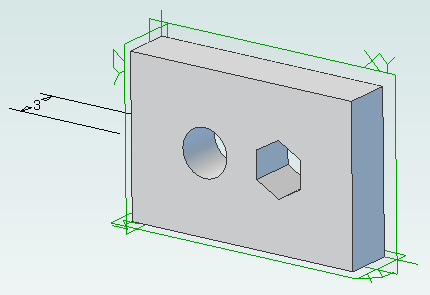
When this script is run it produces the following test part with the regular hole on the left and the polyhole on the right:
To rotate the part simply change the plane used, perhaps to “ZX-Plane”, and run the script again.

Python Scripting with Alibre Design
Apr 3rd
ADScript makes it easy to use Alibre Design with Python scripting. For example creating a new part:
Test = Part("Test")
We can get access to planes in the design workspace, for example:
XYPlane = Test.GetPlane("XY-Plane")
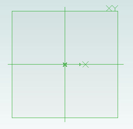
Once we have a part and plane we can create a sketch on the plane:
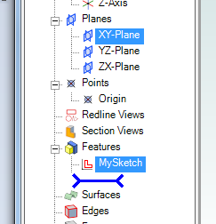
MySketch = Test.AddSketch("MySketch", XYPlane)
Adding to the sketch is easy:
MySketch.AddCircle(0, 0, 10, False)
Now we can extrude it:
Object = Test.AddExtrudeBoss("Object", MySketch, 5, False)
