Interesting Tech Projects
Miscellaneous

868MHz PCB Antenna
Dec 30th
I recently had a need to design an antenna on a PCB for LoRa, an 868MHz long range, low power communications protocol. For this project I decided to use an off-the-shelf LoRa module that already contained an RF matching network. The only requirement was a 50 Ohm antenna that would work at the desired frequency. Space on the board was limited.
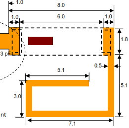
I decided to use a ceramic antenna to save space, selecting the Johanson 0868AT43A0020. The manufacturer has a datasheet showing how the part needs to be placed on a PCB.
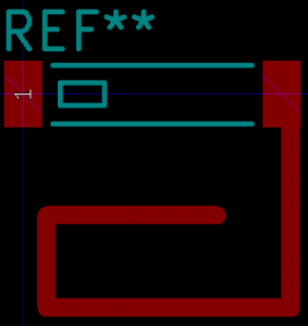
First step was to create a new PCB footprint containing the required layout.
The layout was followed precisely. I used the silkscreen to clearly indicate the orientation of the antenna. Note than only one end of the antenna is given a pin number. The other end is “no connection”. The schematic used a single pin connector component:
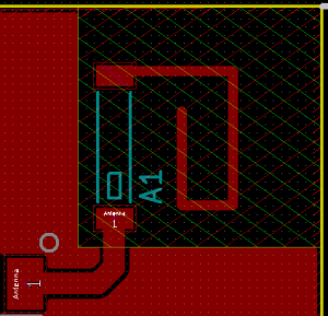
When laying out the PCB a “keep out” area was added to both sides of the PCB, making sure it extended 3mm beyond the antenna per the data sheet.
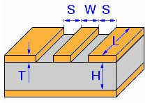
The track from the component pad to the antenna needs to have an impedance of 50 Ohms in order to minimize loss. It also needs to be surrounded by a ground area and have a ground area on the other side of the board. This is called a coplanar wave guide with ground plane.
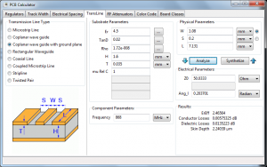
KiCAD has a built in calculator to work out the required track width in order to achieve 50 Ohms impedance. Here are the parameters I used for a standard 1.4mm FR4 two-layer PCB. I played around with the track width until I got close to 50 Ohms.
This gave a track width of 1.08mm when the gap between the ground and the track is 0.2mm (the KiCAD default).
- Er = 4.5 (FR4 PCB material)
- TanD = 0.02 (FR4 PCB material)
- Rho = 1.72e-008 (copper tracks)
- H = 1.6mm (standard two layer board thickness)
- T = 0.035mm (1oz copper thickness)
- S = 0.2mm (gap between ground pour and track on the track side of the board)
- L = 9.554mm (length of the track from pad to antenna)
- Frequency = 868MHz

Generating a Part Library in Geomagic Design
Jul 5th
Introduction
This tutorial demonstrates how to create a library of parts in a CAD neutral format based on a single template part. It takes advantage of parameterization in Geomagic Design.
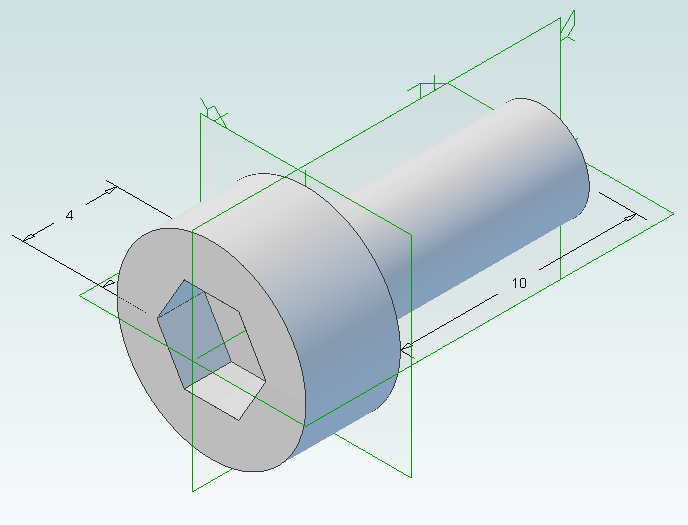
We will start by creating the base part that we will use to create the library. This will be a simple cap head bolt.
Next we will use WizoScript to generate a library of 10 bolts of different lengths.
This type of task is ideally suited to scripting because it handles the tedious repetitive operations needed. While the part demonstrated in this tutorial is simple the same principles can easily be used for complex parts with multiple parameters.
Creating the Template Part
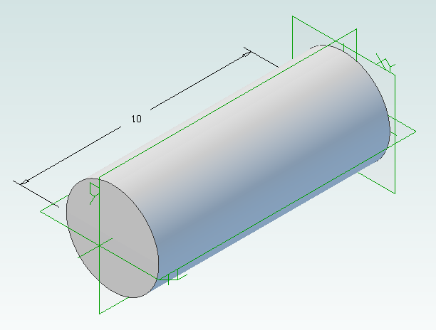
In Geomagic Design create a new part and then a sketch on the XY-Plane. On this sketch draw a circle centered on the origin with a diameter of 4mm and then extrude into a cylinder with a length of 10mm.
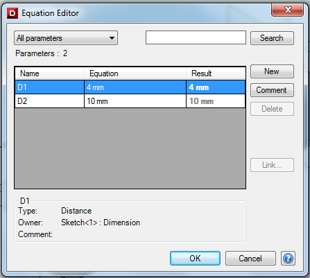
Under the Viewing and Analysis tab click on the Equation Editor button.
Double-click on “D2” and enter “Length” to give the length of the bolt a useful name then close the equation editor window.
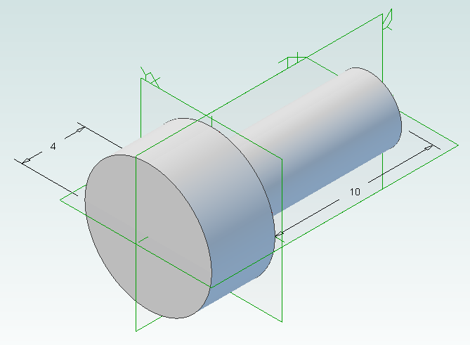
Create the bolt head by adding a sketch to the end of the cylinder on the XY-Plane, setting the diameter to 8mm and extruding 4mm.
Create a new sketch on the top of the bolt head, draw a hexagon with an inside diameter of 4mm and then extrude cut 2mm.
Create a new folder called “PartLibrary” and save as TemplatePart.AD_PRT. Keep the part open in Geomagic to continue with the tutorial.
Writing a Basic Script
Start WizoScript 1.70 or later. When it runs it automatically creates an empty script that we can start using right away.
First we need to tell the script about our template part. For this tutorial the part must be open in Geomagic when the script runs, however it is possible to use a saved part that is not currently open. Please see the WizoScript reference manual for further details.
The following script line tells WizoScript “I have a part open and I want you to use it”:
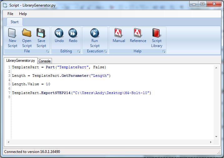
TemplatePart = Part(“TemplatePart”, False)
Next we need to get access to the length parameter that we have already created it. Once we have access to it we can change its value
Length = TemplatePart.GetParameter("Length")
The default units for a script are millimeters, so if we enter the following:
Length.Value = 10
Then we are setting the length of the bolt to 10mm. Enter this into the script.
Now that we have set the length of the bolt we need to export it in a CAD-neutral formal so it can be shared with others. Here is how to do it:
TemplatePart.ExportSTEP214("C:\Users\Andy\Desktop\M4-Bolt-10")
This is what you should have so far:
Save the script and click on the Run button. If there are any errors correct them in the script and try again. If the script is successful you should now have a M4-Bolt-10.stp file.
Generating Multiple Parts
So far it’s not very interesting. We’ve generated a single STEP part that we could have easily created directly in Geomagic Design without needing scripting. Now we will look at generating multiple parts in one go.
The first step is to create a function that is given a length and creates a STEP file. A function is a way of grouping parts of a script together so they can be run over and over again. Edit your script to look like the following:
def GenerateBolt(NewLength):
  Length.Value = NewLength
  TemplatePart.ExportSTEP214("C:\Users\Andy\Desktop\M4-Bolt-"+str(NewLength))

TemplatePart = Part("TemplatePart", False)

Length = TemplatePart.GetParameter("Length")

GenerateBolt(10)
GenerateBolt(12)
We now have a function called GenerateBolt that takes a length and creates a STEP file. The function has to be defined before it is used so put it at the start of the script.
Another key change is that the name of the STEP file contains the length, whatever that may be. This is achieved by appending “M4-Bolt-“ with the length value.
Run the script. It will call GenerateBolt twice and create two STEP files containing a 10mm bolt and a 12mm bolt.
The final step is to create a loop that goes from a minimum length to a maximum length creating bolts. Replace the two calls to GenerateBolt with the following:
MinimumLength = 10
MaximumLength = 20
for NewLength in range(MinimumLength, MaximumLength + 1):
  GenerateBolt(NewLength)
Run the script and it will generate bolts with lengths from 10mm to 20mm.
Here is the final script with comments added to explain:
# Takes a template bolt and creates a library of bolts of different lengths in
# a CAD neutral format

# Creates a bolt of a specific length. NewLength = desired length of bolt in mm
# Saves the bolt to the desktop as a STEP file
def GenerateBolt(NewLength):
  Length.Value = NewLength
  TemplatePart.ExportSTEP214("C:\Users\Andy\Desktop\M4-Bolt-" + str(NewLength))

# Get access to currently opened part that we will used as a template
TemplatePart = Part("TemplatePart", False)

# The template part has a Length parameter defined which we will control
Length = TemplatePart.GetParameter("Length")

# Create bolts from 10mm to 20mm
MinimumLength = 10
MaximumLength = 20
for NewLength in range(MinimumLength, MaximumLength + 1):
  GenerateBolt(NewLength)
Crazy Flight Paths
Apr 20th
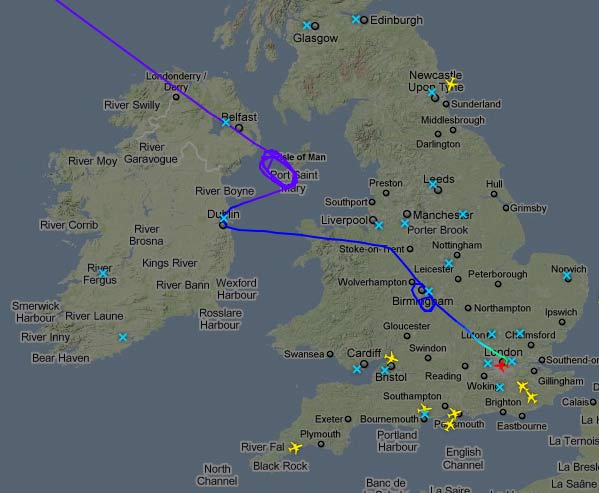
This is the flight path of British Airways BA84 on April 20th 2010 flying from Vancouver to London Heathrow (from FlightRadar24.com):
What happened?
- The flight (Boeing 747) took off from Vancouver while Heathrow was still closed because of ash from the Eyjafjallajokull volcano in Iceland. When it reached the Isle of Man Heathrow was still closed so it was put into a holding pattern for a couple of hours at cruising altitude.
- Other British Airways flights were being diverted to Shannon, Ireland and it looks like the airline and/or ATC gave up and sent the aircraft there, at which point it started descent to 26,000 feet.
- The British Government announced that at 10pm all UK airports would reopen. BA84 then turned back towards Heathrow while over Dublin.
- When the flight reached Birmingham it was put back into a holding pattern, probably because it would have reached Heathrow too early.
- The flight landed at Heathrow at around 9:45pm
Not a flight I would have liked to have been on!
Google Sketchup and Kerkythea – A Perfect Combination
Dec 12th
Google Sketchup is pretty nice. I’ve tried 3D CAD programs in the past but never really invested the time to climb the steep (for me) learning curve. There was a bit of a learning curve with Sketchup, but once I got into the “right” way of thinking it became easy to use. Now I use Sketchup all the time, from drawing diagrams for my CNC hobby, to modeling home projects.
The one problem with Google Sketchup is, well, the output looks like a sketch. But now I’ve found a free renderer that not only has a plugin for Google Sketchup, but is just as easy to use as Sketchup. It’s called Kerkythea.
Install, run, and follow the quick start tutorial and you will be rendering your Sketchup models in less than a hour.
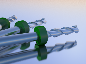
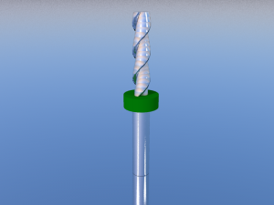
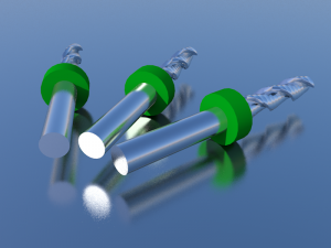
I recently decided to try and model and render some sprial up-cut and down-cut end mills in Sketchup. The results are below.
Replacing AC/Cabin Air Filters and Dealerships
Jun 26th
I know this is a tech blog, but I can’t resist posting this to stop some unsuspecting person from being ripped off…
We have a 2004 Honda Accord. The dealership says we need a new cabin air filter and the cost is $89.99 + tax. I decided to look into doing it myself.
A quick search on Google revealed this video on You Tube showing a 13-year old boy doing it in about two minutes with zero tools. Well, he used his fingers, does that count?
Looks pretty easy. Next a search to find the cost of the filters. Seems to average around $15 + tax and delivery.
I went to PepBoys and got a filter made in the USA with a lifetime warranty for $15.16 including tax. I installed it in the car park in less than a minute.
So I called my local Honder Dealership and talked to the service manager to see what he thought about this. Here are his comments and what I think he meant.
Service Manager: “$89.99. It’s the going rate.”
I think he means: “Everyone else is going to rip you off, so why can’t we?”
Service Manager: “It takes our technicians 15-20 minutes”
I think he means: “You have no clue how much effort it is, so I’ll lie to you”
Service Manager: “It’s Cost Averaging – we charge one price for everyone and some Hondas take a lot of effort to replace the filter”
I think he means: “You have a newer vehicle so you have to pay more to subsidize people with older vehicles”
Service Manager: “One price makes it easier for our customers”
I think he means: “Most of our customers don’t to know, and one price makes it easier for us to remember the price”
Service Manager: “I called the other Honda dealership and they charge $125”
I think he means: “We don’t rip you off as badly as the others so keep coming here”
Service Manager: “Sorry I took so long to call you back to appease you… errr… give you an answer I should say…”
I think he means: “All I do all day is appease complaining customers. Oops, did I say that out aloud?”
Yes, he really did say that. I don’t have a good enough imagination to make this up…
I then called the other Honder dealership. Sure enough they charge $125. When I asked why I was told “It’s labor intensive. There is some assembly required after the filter is changed”. Yeah, right… Snap on the small clip.
So, check around your local dealerships and see if they do “cost averaging”.
