Interesting Tech Projects
Electronics

868MHz PCB Antenna
Dec 30th
I recently had a need to design an antenna on a PCB for LoRa, an 868MHz long range, low power communications protocol. For this project I decided to use an off-the-shelf LoRa module that already contained an RF matching network. The only requirement was a 50 Ohm antenna that would work at the desired frequency. Space on the board was limited.
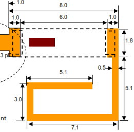
I decided to use a ceramic antenna to save space, selecting the Johanson 0868AT43A0020. The manufacturer has a datasheet showing how the part needs to be placed on a PCB.
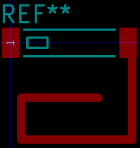
First step was to create a new PCB footprint containing the required layout.
The layout was followed precisely. I used the silkscreen to clearly indicate the orientation of the antenna. Note than only one end of the antenna is given a pin number. The other end is “no connection”. The schematic used a single pin connector component:
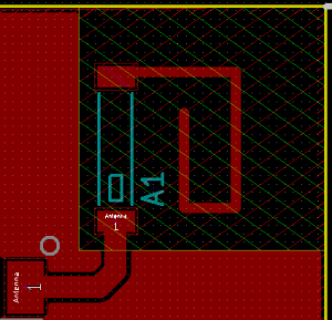
When laying out the PCB a “keep out” area was added to both sides of the PCB, making sure it extended 3mm beyond the antenna per the data sheet.
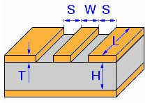
The track from the component pad to the antenna needs to have an impedance of 50 Ohms in order to minimize loss. It also needs to be surrounded by a ground area and have a ground area on the other side of the board. This is called a coplanar wave guide with ground plane.
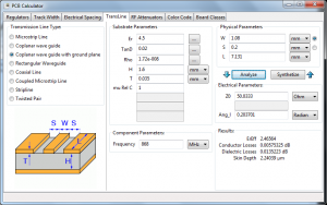
KiCAD has a built in calculator to work out the required track width in order to achieve 50 Ohms impedance. Here are the parameters I used for a standard 1.4mm FR4 two-layer PCB. I played around with the track width until I got close to 50 Ohms.
This gave a track width of 1.08mm when the gap between the ground and the track is 0.2mm (the KiCAD default).
- Er = 4.5 (FR4 PCB material)
- TanD = 0.02 (FR4 PCB material)
- Rho = 1.72e-008 (copper tracks)
- H = 1.6mm (standard two layer board thickness)
- T = 0.035mm (1oz copper thickness)
- S = 0.2mm (gap between ground pour and track on the track side of the board)
- L = 9.554mm (length of the track from pad to antenna)
- Frequency = 868MHz

Halogen Reflow Oven Using Off-the-Shelf Parts
Dec 28th
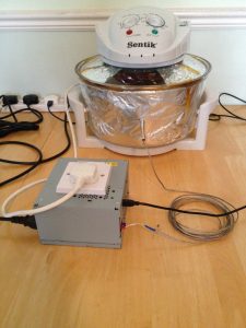
Here is my version of a solder reflow oven for surface mount PCBs. It is a merging of the following two projects, taking advantage of cheap and easy to obtain halogen ovens and off-the-shelf control hardware, avoiding the need to create custom electronics.
- https://apollo.open-resource.org/mission:resources:picoreflow
- http://andybrown.me.uk/2014/05/11/awreflow/
The halogen oven part of the build is identical to Andy Brown’s build. Same oven, same thermocouple, same modifications (remove fat spatter shield, modify fan, install thermocouple).
The software uses picoReflow on a Raspberry Pi Zero W (which has built-in wifi). I have made some improvements to the software which you can obtain from github here: https://github.com/ajayre/picoReflow
- Performs trimmed mean averaging on the temperature values to allow use of noisy thermocouples
- Retries failed MAX6675 connections so it works at power on reset from /etc/rc.local
- Added a temperature compensation offset
- Removed check for sudden temperature increases (allows PID step and bump tests)
- Uses PID with 2Hz PWM taken from Andy Brown’s code
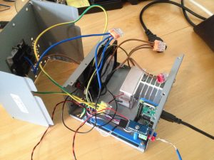
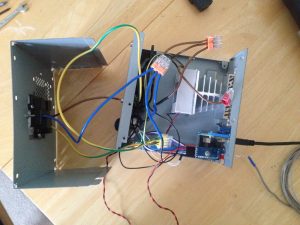
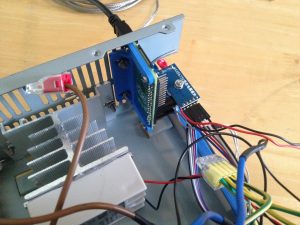
I made some changes to the power/control system. Like Andy Brown I used an old desktop PC PSU case. I removed everything from it except for the power connector. Into the case I put:
- SSR relay and heatsink
- 240V 80mm case fan
- Raspberry Pi Zero W
- MAX6675 thermocouple IC
The connections are very simple. The relay and the fan are connected to 240V. The MAX6675 is connected to the Raspberry Pi and the Raspberry Pi controls the relay. The fan is always on when power is applied.
I also added a push button connected to a Raspberry Pi GPIO. When pressed it runs a simple python script that shuts the Raspberry Pi down cleanly.
I 3D printed a couple of brackets to mount the electronics in the case – they are blue in the pictures. In order to connect the Raspberry Pi to a USB cable for power I removed part of the grille.
I am initially testing with lead-based solder, so I copied the reflow profile from here: 

PCB For Raspberry Pi WH1080 Weather Station
Nov 15th
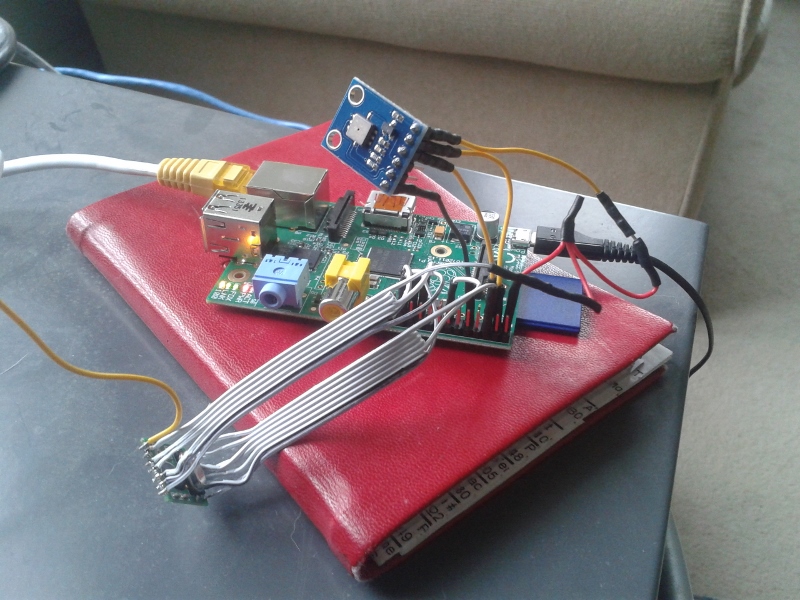
Previously I wrote about using a Raspberry Pi to receive 433MHz signals from a WH1080 weather station. This is the mess of wiring I came up with:
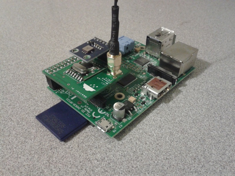
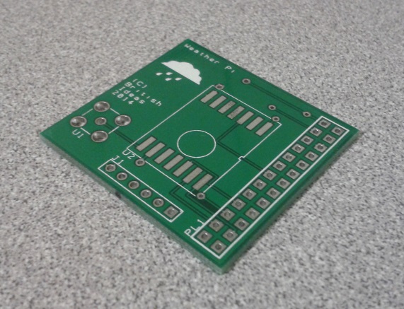
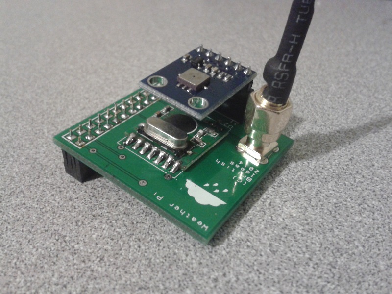
This worked fine until it stopped. I probably didn’t crimp a wire properly and too many knocks resulted in unreliable operation. To solve this I designed a PCB that connects the radio receiver, pressure sensor and an antenna to a Raspberry Pi:
The design is very simple:
It accepts a surface-mount version of the RMF01 module (the version with a black resin blob). This is easily soldered onto the PCB by hand.
A female through-hole SMA connector is used for the antenna connection. This allows a range of off-the-shelf antennas to be used. The one I purchased from eBay didn’t work so I modified it as can be seen in the pictures. Alternatively a wire can be directly soldered to the board.
Finally a six pin BMP085 module is connected to a header. The pinout of the BMP085 module used is:
- Pin 1 = 3.3V
- Pin 2 = SDA
- Pin 3 = SCL
- Pin 4 = No connection
- Pin 5 = No connection
- Pin 6 = Ground
Here is how the PCB looks when populated:
Download the schematic diagram (15MB).
I have some spare boards, so if you would like one to experiment with please contact me.
Update: All the spare boards are gone. I hope everyone who received one has a lot of fun with them!
Here are the gerber files, suitable for submitting to a PCB house. The license is CC-BY-NC SA. I.e. for personal non-commercial use only. Sorry, but I am unable to provide support for these files.

Tenting Vias in DesignSpark PCB
Oct 10th
Sometimes it is useful to cover vias with solder mask. Here is how to do it in DesignSpark PCB. First the solder mask with the vias exposed:
1. Choose Design Technology… from the Settings menu
2. Click on the Solder Mask row and then the Edit… button
3. Uncheck the Vias setting and click on OK.
4. Click on OK to close the dialog window.
At this point the solder mask should automatically update to show the vias are now covered. If it doesn’t deselect the layer and reselect it to force a refresh.
