Interesting Tech Projects
Andy
Located in Tucson, Arizona, USA
Homepage: http://www.britishideas.com
Posts by Andy

Scripting Polyholes in Alibre Design
Apr 6th
3D printing by using layers of melted plastic filament, such as used by RepRap printers, causes small holes (less than 15mm in diameter) to end up smaller than the designed size. To compensate for this people create designs with larger holes so they shrink to the right size. It’s not an ideal solution – how much do they need to be increased by? What if you later want to send the same design to a commercial printing service that is more accurate?
The RepRap developer Nophead examined this issue and came up with a simple way to design holes that print at the right size regardless of the printing method. He called them polyholes.
In short the solution is to approximate the hole with a polygon and increase it’s size slightly.
Creating these polyholes in a CAD package is tedious. The size has to be calculated and the number of sides varies with the hole size. ADScript has this functionality baked right in. Here is an example python script:
# use millimeters for all values
Units.Current = UnitTypes.Millimeters

# test block dimensions
length = 15
width = 10
depth = 3
# size of test holes
diameter = 3

# create a new part, get the XY plane and create a sketch on the plane
PolyholeTest = Part("PolyholeTest")
XYPlane = PolyholeTest.GetPlane("XY-Plane")
Base = PolyholeTest.AddSketch("Base", XYPlane)

# draw the part outline
Base.AddPolyline([0, 0, length, 0, length, width, 0, width, 0, 0], False)
# draw a regular hole
Base.AddCircle(length / 3, width / 2, diameter, False)
# draw a polyhole
Base.AddPolyhole(length / 3 * 2, width / 2, diameter, False)
# extrude the sketch into a part
PolyholeTest.AddExtrudeBoss("Block", Base, depth, False)

# save and export to STL for printing
PolyholeTest.Save("C:\Users\Andy\Desktop")
PolyholeTest.ExportSTL("C:\Users\Andy\Desktop\PolyholeTest.stl")
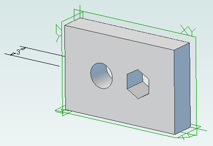
When this script is run it produces the following test part with the regular hole on the left and the polyhole on the right:
To rotate the part simply change the plane used, perhaps to “ZX-Plane”, and run the script again.

Python Scripting with Alibre Design
Apr 3rd
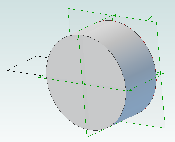
ADScript makes it easy to use Alibre Design with Python scripting. For example creating a new part:
Test = Part("Test")
We can get access to planes in the design workspace, for example:
XYPlane = Test.GetPlane("XY-Plane")
Once we have a part and plane we can create a sketch on the plane:
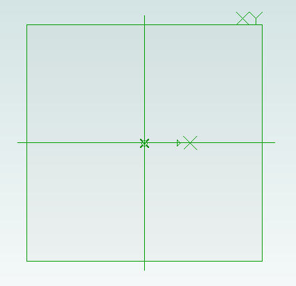
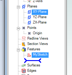
MySketch = Test.AddSketch("MySketch", XYPlane)
Adding to the sketch is easy:
MySketch.AddCircle(0, 0, 10, False)
Now we can extrude it:
Object = Test.AddExtrudeBoss("Object", MySketch, 5, False)

Using Alibre Design for 3D Printing of Multi-Part Projects
Mar 13th
The easiest way to design projects that involve multiple parts in Alibre Design is to create and edit parts inside an assembly workspace. This allows the edges and cross-sections of one part to be reused in another part which is very useful.
However for 3D printing there is a downside – creating a part inside an assembly results in that part being orientated the same way in the part workspace as it in the assembly workspace. For 3D printing we want a specific side face down on the XY plane. That choice of side depends on the part.
So we have taken advantage of the tools and features that Alibre Design offers but we now have parts that are not orientated correctly for printing. They can be rotated in Alibre Design by creating a new assembly just for that part but there must be an easier way.
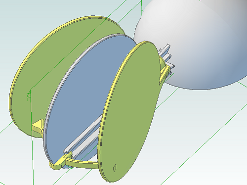
The following screenshot illustrates the problem. The circular panel is in an assembly and orientated the way we need it to check that everything fits together.
Opening the part in it’s own workspace shows the orientation.
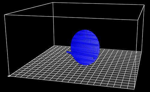
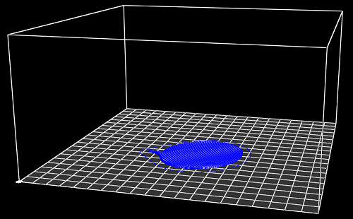
Exporting and slicing this part as it is results in the following g-code.
So how can we make this easier, especially if we have an assembly with lots of parts? By using an add-on for Alibre Design.
I’ve updated my AD Assembly Exporter utility that I have previously written about. It can now automatically rotate STLs when they are exported so that the desired face is aligned with the XY plane.
First you must choose the face that will be placed on the print bed.
- Edit the part
- Right-click on the face and choose Insert Plane..
.
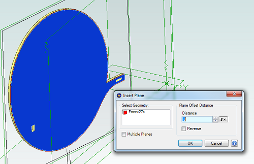
- Click on OK
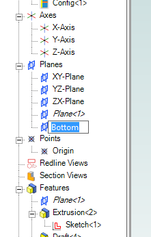
- In the Design Explorer right-click on the new plane and choose Rename
- Enter the name “Bottom”
Now save the part and open the assembly containing it, if it wasn’t already open. Repeat this for all parts in the assembly that will be printed.
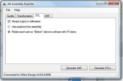
Run AD Assembly Exporter, click on the STL tab and choose the option to rotate using the “Bottom” plane.
Then click on Generate STLs. Here is the new g-code output:

Leveling a RepRap Bed with Three Screws
Mar 3rd
The majority of beds on RepRap 3D printers are leveled using four adjustment screws, one at each corner, and therefore most if not all leveling instructions are for that situation. The RepRapPro printers are different in that they have only three screws and there is little detailed information on how to use them to level the bed. Here are the steps I use.
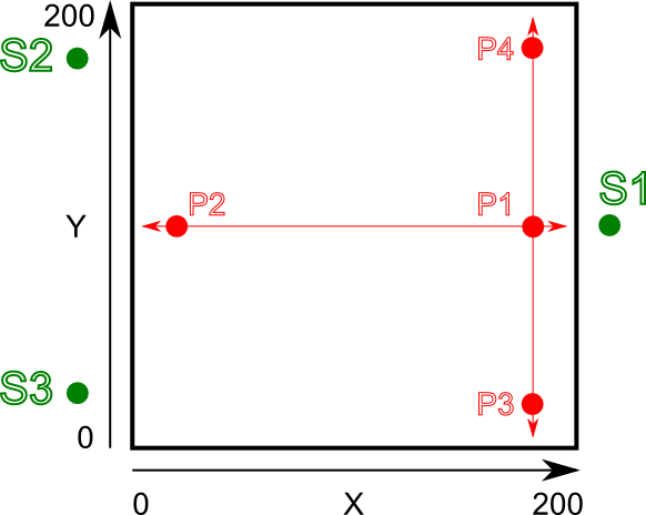
This is a view of the bed looking from above and standing at the front of the printer.
The home position of X = 0, Y = 0 is at the bottom left. Green dots indicate the positions of the adjustment screws for leveling the bed. Red dots indicate the measurement positions of the hotend (the nozzle). It is important to note that when at normal operating temperature the bed and hotend move closer together through expansion from the heat. Therefore leveling must be performed while hot.
- Set the bed to 60C and the hotend to 150C. I use a slightly lower temperature on the hotend to stop oozing of filament during the process. You can optionally retract or remove the filament if you prefer
- Loosen all three adjustment screws, S1, S2 and S3. I.e. the bed is raised to it’s maximum height while still being securely attached to the Y axis.
- Move the Z endstop thumbwheel to a conservative position so that when Z is homed the hotend won’t crash into the bed.
- Move hotend to position P1 (X = 200, Y = 100)
- Repeatedly adjust the Z endstop thumbwheel and home the Z axis until the hotend is the thickness of a piece of paper above the bed.
- Move hotend to position P2 (X = 0, Y = 100) and home Z
- We now need to adjust the height of the bed so that the hotend is the thickness of a piece of paper above the bed. The left side of the bed can be raised and lowered by adjusting screws S2 and S3 in parallel – i.e. turning them both in the same direction and by the same amount.
- At this point the hotend should now be perfectly aligned with the bed along the horizontal red line shown in the diagram. What we still don’t know is if the bed is tilted towards the front or back, which we will now check.
- Move the hotend to position P3 (X = 200, Y = 0) and home Z
- Adjust the height of the front right corner of the bed so that the hotend is the thickness of a piece of paper above the bed. This corner can be adjusted by using screw S2 only. For example, if we turn S2 clockwise we will lower the rear left corner which will raise the front right corner, moving it closer to the hotend.
- Move the hotend to position P4 (X = 200, Y = 200) and home Z
- Adjust the height of the rear right corner of the bed so that the hotend is the thickness of a piece of paper above the bed. This corner can be adjusted by using screw S3 only. For example, if we turn S3 clockwise we will lower the front left corner which will raise the rear right corner, moving it closer to the hotend.
- At this point the hotend should now be perfectly aligned with the bed along the vertical red line shown in the diagram. Alignment in two directions means that the entire bed should be level. The problem with the two previous adjustments is that they slightly affect other areas of the bed at the same time, which we don’t want. The way to minimize this is to now repeat the process again by going back to step 4.
- Finally double-check the height of the hotend above the bed at the center (X = 100, Y = 100). It should be the thickness of a piece of paper.

Using Alibre Design for Multi-color and Multi-material 3D Printing Part II
Feb 27th
Previously I wrote about my little utility that allows exporting properly positioned STLs from Alibre Design so they can be imported into a slicing program for multi-color printing. This is fine for use with the RepRapPro slicer but perhaps not with other slicers.
Slic3r is a very popular, fast and flexible slicing program and now it also supports printing multi-color objects. The file format chosen by it’s author is AMF – Additive Manufacturing File. It is essentially a way to group STL files together into a single object and specify different colors or materials for various parts.
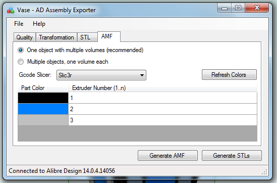
I’ve now updated my exporter utility to support saving Alibre Design assemblies directly to this format:
When an assembly is opened the application obtains the colors used by the parts in the assembly. It is then possible to assign the colors to extruders on the 3D printer. For example in this image black is the body of the object and has been assigned to the primary extruder. It’s necessary to choose which slicing program is being used as there isn’t a standard way of mapping colors to extruders. In particular Slic3r currently has several limitations so by choosing Slic3r the application will stop you from making invalid choices.
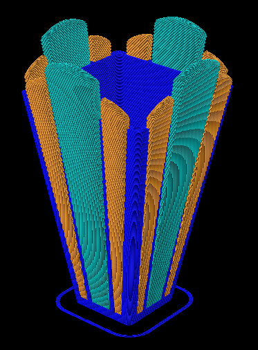
Once generated the AMF file can be loaded directly into Slic3r and sliced. Here is the g-code output shown in Repeiter-Host:
Note that the colors don’t match the Alibre Design assembly because Repetier-Host uses it’s own coloring scheme to represent the different extruders. For example blue is always the first extruder.
Now the object is ready to be printed. The estimated print time for this example is five hours and 45 minutes.

Ray Tracing (Rendering) with Alibre Design PE
Feb 15th
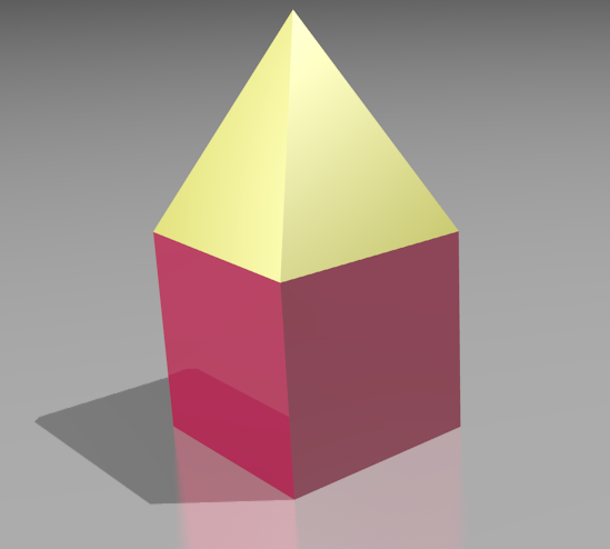
The Professional and Expert versions of Alibre Design come with a ray tracer called Keyshot but the Personal Edition of Alibre Design does not. However it is easily possible to use the free and very powerful Blender to generate ray traces of your 3D models.
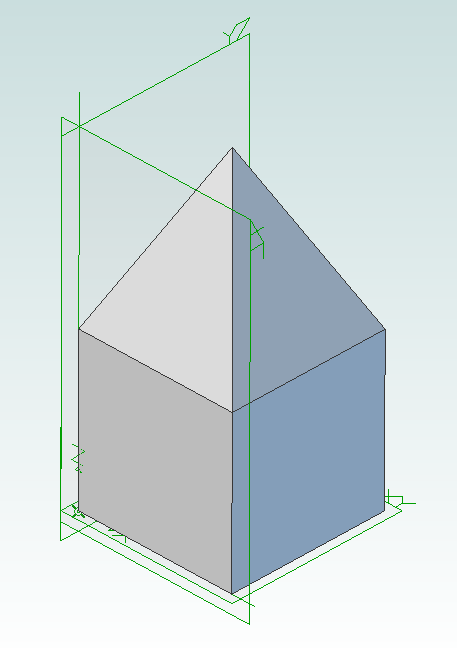
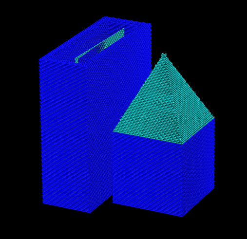
First you must design the parts in Alibre Design and put them together into an assembly. For example here is an assembly showing a pyramid stacked on top of a cube.
Now use my free utility AD Assembly Exporter to export the assembly as a set of STL files. You can download the utility from here. More details on using it can be found in my previous post on 3D printing with Alibre Design.
Next install and run Blender.
Press Delete to delete the default cube. Then go to File -> Import -> STL and choose the STL files that were generated. They will appear in the view in the same positions as they were in the assembly in Alibre Design.
Optionally you can select all the STLs and press ‘S’ to scale them down as they may be a bit large. Now you can assign materials, add lights, position the camera, etc. to render the scene.

Using Alibre Design for Multi-color and Multi-material 3D Printing
Feb 14th
When you wish to print out a part on a 3D printer the workflow is simple – design the part, export to STL and print it. This is fine when you are only printing with a single material or color. Becoming increasingly popular and affordable are 3D printers that support printing with two or three colors/materials at once, such as the Prusa Mendel from RepRapPro. How can Alibre Design be used for this scenario?
In general the easiest way to allocate different colors/materials to a part is to design that part using multiple smaller pieces. Each piece is assigned a color/material for printing. Alibre Design has a very flexible and easy to use way of grouping parts together called an assembly. What we would need therefore is a way of exporting multiple STLs from an assembly preserving their relationships to one another.
For example, suppose we have a cube and a pyramid and we wanted to place the pyramid on top of the cube and print it in a different color to the cube. We would design the cube and pyramid as two parts then use an assembly to stack the pyramid on top of the cube. Now we need to export the two STLs preserving their position relative to the same origin. This would allow the 3D slicing software to know to stack the pyramid on top of the cube. This is where the problems start.
Alibre Design supports exporting an assembly to a single STL. It merges all the parts together and produces a single object. Information about the individual parts is lost, so this is not usable for our purposes. If you export an individual part or you hide/suppress parts in an assembly then Alibre Design exports the STL using the position and origin in the part file not the assembly, causing the position information to be lost.
An additional problem is the units used in STL files are not defined. If you create a part using centimeters then Alibre Design exports an STL that uses centimeters. Likewise if you create a part using inches then the STL uses inches. The problem is that most, if not all, 3D slicing software assumes the units are millimeters. Solving this for a single part is easy – simply change the units used to millimeters before exporting. However an assembly can be made from multiple parts that all use different units. Regardless of the units chosen for the assembly the STL export will always use the units the part was designed with.
There is one more issue that needs to be addressed. When creating an assembly parts become rotated but the final positions may not be the best for 3D printing. Consider the lid for a box. When creating the assembly it will be rotated so the top is facing upwards but the optimal orientation for printing is probably for the top to be facing downwards onto the build surface. Currently the easiest way to rotate an assembly is to place it into a new assembly as a sub-assembly. This creates an unnecessary extra file and step to perform.
Fortunately Alibre Design has an easy to use API that allows these problems to be solved and I present here my free utility with an exciting name: AD Assembly Exporter.
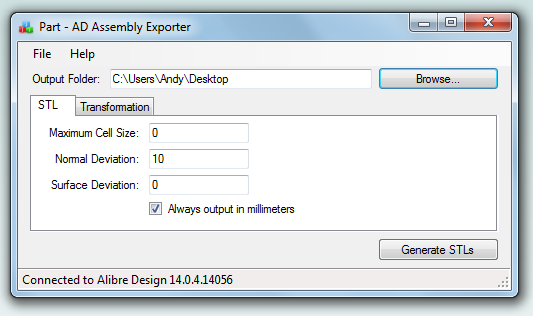
To use start the application and Alibre Design and open an assembly. In the assembly you can optionally hide/suppress parts you do not want to export. The name of the assembly will be shown in the title bar of the AD Assembly Exporter application. Enter the desired settings and click on the Generate STLs button.
The utility supports forcing the units in STLs to millimeters and rotation around an axis. The STL export options match those found in Alibre Design so please see the Alibre Design manual for a description of what they do. Sub-assembly nesting is supported.
Only open one assembly at a time when using the utility. It will export the first assembly found from your open Alibre Design sessions.
Please note that this software is provided “as-is”. More details can be found in the license shown during installation.
Click here to download AD Assembly Exporter (now called WizoPrint)
Setting Up A PC for Android Development
Nov 16th
The steps are confusing, the requirements many and it entails reading multiple web pages then fitting the jigsaw together. Here are the exact steps I took to set my Windows PC up for development with Android.
- Download “Eclipse IDE for Java Developers“.
- Extract the files using 7-zip and then copy to C:\Program Files\Eclipse
- Download and install the Oracle JDK (Standard Edition)
- Download and install the Android SDK
- At the end of the installation choose to run the SDK manager.
- Check/Tick Android 2.3.3 then then click on the Install button.
- Download and install the ADT Plugin using these steps. Note that the instructions say that a “Welcome to Android Development” window will appear. It won’t. Ignore that.
- In Eclipse go to Window -> Customize Perspective…
- Click on the Menu Visibility tab
- Expand File and then New and check/tick Android Application Project
- Click on OK
- In the main Eclipse window click on the icon to go to the workbench.
- Follow the first lesson

Improved RepRapPro Mendel Cooling Fan Bracket
Oct 15th
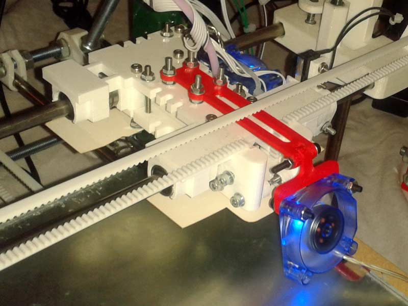
Previously I wrote about a bracket I designed to attach a 40mm chipset fan to a RepRapPro Mendel. Here I present an improved version.
This version attaches to the X carriage which means the fan is closer to the hotend. With this I was able to print out a tree frog with no support structure.
Details and the STL files can be found on Thingiverse.

Setting up Raspberry Pi for 3D Printing with RepRap
Sep 29th
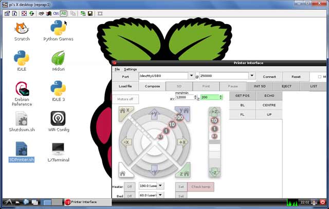
Having a 3D printer is cool, but requires a PC to be attached to it for control and monitoring (things like jogging, setting temperatures and even sending the gcode). Wouldn’t it be nice if the PC was a small circuit board attached to the printer making it a compact all-in-one solution? Here is how to use a Raspberry Pi $25 PC to do exactly that!
Goals:
- Use VNC to remotely view the desktop on the Raspberry Pi
- There are two scripts on the desktop – starting pronterface and shutting down.
- gcode files on a server are automatically available on every boot
- 250000 baud works fine
- Set up without connecting a TV, keyboard or mouse
1. Download the current version of Raspian. Beginning sometime in September an important USB problem was solved. I used the September 18th version and it works fine.
2. Download an application to copy the image file to an SD card. I used Win32DiskImager along with an 8GB SDHC SanDisk card. A fast card is important.
3. Insert the SD card into the Raspberry Pi, attach to a wall-wart USB power source, connect an ethernet cable and turn on the power.
The LEDs will turn on and flash a lot. The boot process should finish after a couple of minutes.
Now you have to find out the IP address that has been assigned to the Raspberry Pi. Probably the easiest way is to log into your router and look at the connected devices. If your router is like mine then it shows “raspberry pi” as the device name and clicking on it gives the IP address.
Next connect using a SSH terminal application. I recommend PuTTY. Enter the IP address and log in with username “pi” and password “raspberry”. Then enter:
sudo apt-get update
sudo apt-get dist-upgrade
sudo apt-get install git-core
sudo wget http://goo.gl/1BOfJ -O /usr/bin/rpi-update && sudo chmod +x /usr/bin/rpi-update
sudo rpi-update
sudo reboot
After the reboot log back in and:
sudo apt-get install tightvncserver
tightvncserver
vncserver :1 -geometry 1024x728 -depth 24
When prompted for a password enter what you want to use to protect access to the printer. For example I used “reprap”.
Test you can connect and view the desktop by installing TightVNC on your PC and connecting using the IP address with “:1” after it. For example my Raspberry Pi was at 192.168.1.150:1.
Follow the instructions given here to assign a static IP address and start the TightVNC server on boot. Test by rebooting and connecting using TightVNC.
You can edit /etc/hostname and /etc/hosts to change the name from raspberrypi to something like reprap, if you desire.
Create a script on the desktop to shut down the Raspberry Pi when it is double-clicked:
cd ~/Desktop
touch Shutdown.sh
chmod 777 Shutdown.sh
nano -w Shutdown.sh
Enter into it:
#!/bin/bash
shutdown -h now
Test that double-clicking on the file and choosing “Execute” causes the Raspberry Pi to shut down.
Add the user pi to the dialout group so that the USB serial ports can be used:
sudo usermod -G dialout pi
Expand the filesystem to use the entire SD card:
sudo raspi-config
Choose the item from the menu to expand the root partition.
Run raspi-config again and choose the overclocking option and select a faster speed. Currently I’m not sure which are unreliable (if any!).
Download printrun and put it somewhere useful, for example /home/pi/3DPrinting.
Install the dependencies for printrun:
sudo apt-get install python-serial python-wxgtk2.8 python-tk git-core
Create a script on the desktop to run pronterface when it is double-clicked:
cd ~/Desktop
touch 3DPrinter.sh
chmod 777 3DPrinter.sh
nano -w 3DPrinter.sh
Enter into it:
#!/bin/bash
cd ~/3DPrinting
./pronterface.py
Test it by double-clicking on the file.
Follow these instructions to remove the graphical display from pronterface.py so it uses less CPU time.
I wanted to be able to put gcode files on my server and immediately have access to them on the Raspberry Pi. This avoids the need to copy files around. I achieved that by mounting a Samba share on the Raspberry Pi on every boot. This is mostly cribbed from here.
sudo mkdir /etc/sambapasswords
sudo chmod 700 /etc/sambapasswords
sudo nano /etc/sambapasswords/myserver
Enter into the file:
username=windowsusername
password=mypassword
Save and then:
sudo chmod 600 /etc/sambapasswords/myserver
sudo mkdir /mnt/myserver
sudo nano -w /etc/fstab
Enter a new last line with (change the IP address to that of your server):
//192.168.1.52/3DPrintingFiles /mnt/myserver cifs credentials=/etc/sambapasswords/myserver 0 0
Test with:
sudo mount -a
That’s it!
