Interesting Tech Projects
Andy
Located in Tucson, Arizona, USA
Homepage: http://www.britishideas.com
Posts by Andy

WH1080 Weather Station and Weather Underground
Jun 7th
A couple of years ago I bought a WH1080 weather station (e.g. Fine Offset, Mapin). It’s available under many brands from many outlets all over the world and is very common. Here are pictures of what this cheap weather station looks like:

I had the touchscreen connected to a Linux sever via USB and used pywws to upload to Weather Underground. This worked well until USB broke so I had to look for a new solution.
Kevin Sangeelee had developed some code that allowed a Raspberry Pi to receive the 433MHz radio signals and decode them. It also had support for a pressure sensor. Perfect. The code can be found here: http://www.susa.net/wordpress/2012/08/raspberry-pi-reading-wh1081-weather-sensors-using-an-rfm01-and-rfm12b/
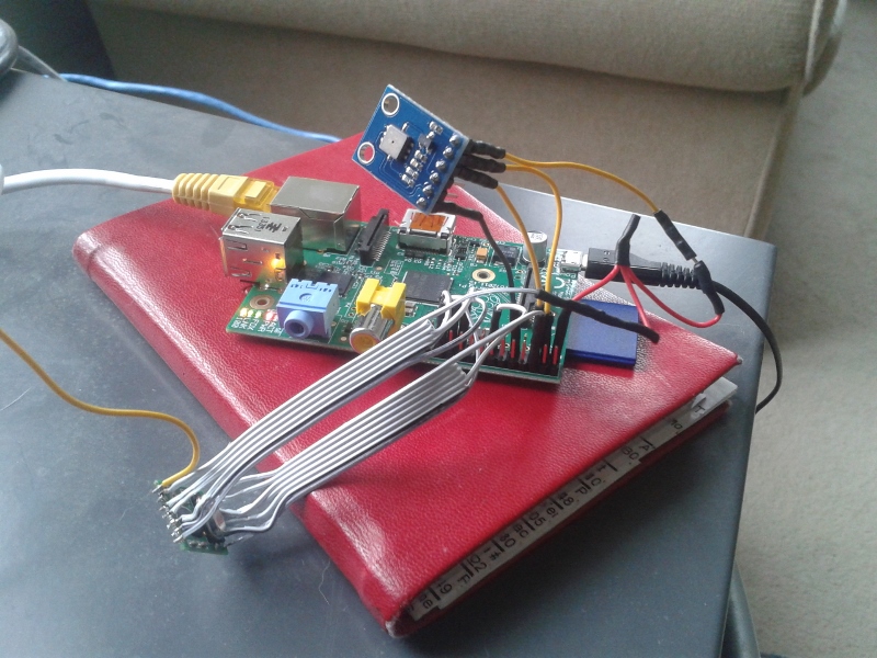
The RFM01 was obtained from Maplin for about £4 and was trivially connected to the RPi. Kevin’s article gives the connections. Note: I didn’t use any resistors.
The BMP085 was also easily connected. Purchased from eBay for about £6 it connects directly to the I2C pins. Again, no resistors needed.
The first step was up update Kevin’s code for revision 2 of the RPi. This is required because a GPIO pin has changed and the second I2C bus is now used.
Now I ran into a stumbling block – how to get the data into pywws. I hoped that this problem had already been solved but unfortunately I would have to start writing custom python modules. After thinking about it for a while I decided that all I needed was to upload data to Weather Underground. I didn’t need the other features of pywws. Fortunately Weather Underground has a simple way of uploading using a HTTP GET request. The data just needed to be massaged into the correct format. While I was at it I decided to use the rapid-fire updating. This means that Weather Underground displays new data from your station roughly every 48 seconds – you can watch it continually update.
You can get the code from GitHub here: https://github.com/ajayre/WH1080-Weather-Underground.
Create a text file in the same folder as the executable called wunderground_creds.txt. On the first line enter the name of your weather station ID, for example IWESTYORKS30. On the second line enter your Weather Underground password.
Compile, run and follow Kevin’s instructions for setting up and tuning. Don’t forget to enable the SPI and I2C modules on the RPi. Also make sure you run:
sudo dpkg-reconfigure tzdata
to set the timezone.
Make sure the path to the credentials file in wunderground.c is set correctly. To start the program on boot I used the following in a boot script:
sudo screen -d -m /home/pi/weather/wh1080_rf
Jack the Ripper Bot V – Troubleshooting
Sep 7th
Part 1 introduced the project, part 2 covered the mechanics and part 3 the electronics. Part 4 covers the software side and part 5 is about troubleshooting.
1. Troubleshooting
- loosen the screws holding the servo and move it back slightly so the gears are still meshing but there is no sideways pressure on the servo shaft.
- make sure the pivot servo is not near the limit of it’s range at any point. When near the limit it will attempt continuous rotation and will lose it’s position.
- check the hub retainer is not touching the lower bearing.
- move the gear housing away from the servo and make sure it rotates freely.
- rotate the in tray outwards slightly and update the in tray position in config.xml. This will move the center of the in tray slightly further from the center of the pivot.
- make sure y axis is vertical (see item 6).
- rotate the out tray outwards slightly and update the out tray position in config.xml. This will move the center of the out tray slightly further from the center of the pivot.
- make sure y axis is vertical (see item 6).
- make sure both sides of the grabber are vertical.
- raise the toolhead microswitch so that more of the grabber is lowered into the hole in the center of the disc.
- make sure that the y axis is exactly horizontal.
- make sure that the y axis is exactly horizontal.
- check that the Y axis is vertical (see item 6).
- make sure that both sides of the grabber are vertical.
- make sure the hub retainer is close to, but not touching, the lower bearing.
- loosen the nuts holding the gear housing to the threaded rod and re-tighten while pressing down on the rear of the gear housing.
- check the y axis is securely attached to the threaded rod.
- adjust the two M8 nuts on the threaded rod at the hub to shorten/lengthen the arm from the pivot to y axis. Make sure the grabber is exactly over the center of the disc.
- tweak the drive tray position in config.xml
2. Ideas for Improvements
- Increase DVD capacity for faster PCs.
- Redesign main gear housing to use less plastic.
- Sugru veneers for grippers.
- Eliminate Raspberry Pi.
– merge BotServer into JacktheRipperBot.exe
– PC communicates directly with Pololu Maestro - PC farm for faster ripping
– use Raspberry Pi to create image of discs which are then put into a queue. A farm of PCs work on encoding the queue. - Cable management on top of support ring to keep wires away from gears.
- Stack two or three DVD drives vertically so the robot can load and unload into all of them.
- Add support for ripping “profiles” to JacktheRipperBot.exe, allowing different Handbrake settings to be used for specific discs in the in tray.
Jack the Ripper Bot IV – Software
Sep 6th
Part 1 introduced the project, part 2 covered the mechanics and part 3 the electronics. Part 4 covers the software side.
1. Maestro
Install the Pololu Maestro software and then connect the Maestro to your PC and start the software.
The microswitches should already be displaying their status. Press the switches and make sure they are working.
Enable the three servo channels and manually move each servo to make sure it works.
Use the software to position the arm over the in tray, DVD drive and out tray. Make a note of the servo position values. Be careful not to go near the limits of the servo as it turns into a continuous rotation servo and loses position.
Use the software to work out a slow speed for raising and lowering the toolhead and also the value to make it stop without the servo making a buzzing sound. Make a note of these values.
Finally use the software to determine the servo values for the grippers being fully open and fully closed. Make a note of these values.
2. Tweaking
Open the DVD tray and put a DVD into it.
Use the two M8 nuts next to the hub to adjust the length of the arm so that the grippers are directly above the hole in the DVD.
Swing the arm over the in tray and check if the grippers are positioned over the center. If not swing the tray outwards slightly or add M8 washers as spacers between the tray and the tray anchor. If you move the tray then you will need to check again the servo value need for the in tray position.
Repeat this for the out tray.
3. Raspberry Pi Setup
Copy to the Raspberry Pi (RPi) the following:
- BotServer.exe
- config.xml
Edit config.xml in a text editor and insert the servo values you have worked out.
Mono needs to be installed on the RPi but the version in the repositories does not work. Instead use the version found here.
Run the server with:
mono ./BotServer.exe config.xml
Open the DVD tray and put a DVD into the in tray.
Load a disc by visiting: http://192.168.1.70/botapi/?command=loaddisc
Replace the IP address with the address of your RPi. The disc should be loaded into the tray.
You may have to adjust the YAxisLowertoDriveTime in config.xml which is given in 1/1000th of a second and governs the time spent lowering the toolhead before dropping the disc into the drive tray.
Once the load disc function is working test the unloading with: http://192.168.1.70/botapi/?command=unloaddisc
The YAxisLowertoOutTrayDropTime in config.xml governs the time spent lowering the toolhead before dropping the disc into the out tray. It has to drop from low enough that it consistently goes into the tray, but high enough that when the stack in the out tray is full there is space to drop the last disc.
4. PC Setup
Copy the following files to your PC:
- JacktheRipperBot.exe
- Rip.bat
- ScanningFinished.bat
Make sure the full .NET Framework 4.0 is installed. If you need to install it then reboot before running JacktheRipperBot.exe.
Install DVDFab Passkey or AnyDVD. Both applications have the option to execute a command when scanning of a disc has completed. Set this up to run ScanningFinished.bat.
Install Handbrake and check the correct path to HandbrakeCLI.exe is used in Rip.bat.
Start JacktheRipperBot.exe and enter the IP address of your RPi.
Go to the advanced tab and try the various operations individually.
Once you are happy everything is working enter the number of discs in the in tray and click on Start to start ripping!

Jack the Ripper Bot III – Electronics
Sep 5th
Part 1 covered the introduction and part 2 the mechanics. Here is part 3 that shows the electronics side.
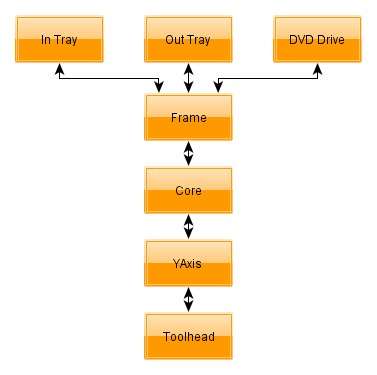
The following block diagram shows the arrangement of the electronics.
For wifi connect a USB wifi interface to the Raspberry Pi (RPi). Connect a USB cable from the RPi to the Maestro. I connect to the RPi via SSH and I have configured my router to always assign the same IP address.
The Maestro requires a separate 5V power supply for the servos.
Connect the servos to the Maestro as follows:
- Channel 0 = Core servo for pivoting
- Channel 1 = Y axis servo
- Channel 2 = Toolhead servo
Use the servo extension cables for the Y axis and toolhead servo.
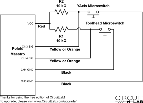
Wire the microswitches as shown in this diagram. I used servo extension cables and the colors mentioned reflect that. Note that the signal wire could also be white.
The 5V connection to the Maestro is not the one on the servo connectors. There is a separate 5V and GND along the top edge. See this section of the Maestro user’s guide for details.
Solder a two pin header onto the pads for the 5V and GND. Use the two way molex connector and 0.1 inch pins to create a connector to plug onto the header. Note that the ground pin is not used, instead the ground on the servo connectors is used.

Jack the Ripper Bot II – Mechanics
Sep 4th
Part I covered the introduction to the robot. This part covers the mechanical assembly.
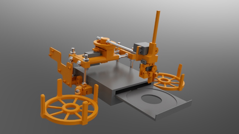
I divided the mechanical design into several groups, which I will refer to throughout. These names are also used for the part designs.
The frame holds everything together. It attaches to the DVD drive. Onto the frame is the in and out trays and what I call the “core”. The core is the main pivoting mechanism for the arm that loads and unloads discs.
At the end of the arm is the YAxis which raises and lowers discs. This should have been called the ZAxis but C’est la vie…
Finally the toolhead is at the bottom of the YAxis and grabs and releases discs.
General Notes
I printed all parts in PLA with three perimeters and 20% fill.
No support is required. The STLs are already correctly orientated.
Any STL name ending in _X2.stl means print two copies of that part.
Whereever M8 nuts are used always use a M8 lock washer against the nut, unless the nut goes into a nut trap.
Exploded diagrams don’t show M8 lock washers, M3 hardware or M2 hardware.
Filing of the printed parts may be needed, especially for the M2 nut traps and if the first layer has a lip because it was squashed.
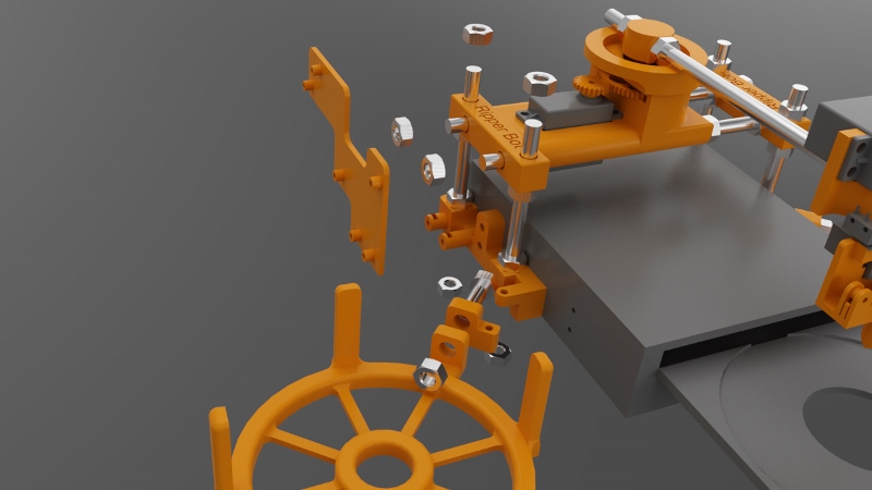
If you are unsure about any step you can download a 3D PDF of the entire robot. Open in Adobe Reader and click on the image. You can then spin the model around and zoom in to examine it from every angle.
1. DVD Drive
The DVD drive must be an internal 5.25 inch type designed to be used horizontally. The tray electronics must open and close the tray fully by pressing the front button on the drive. When the tray is open it must be possible to lower a disc into the tray vertically. I.e. make sure the front of the drive does not overhang the back of the tray slightly.
2. Frame
Attach the left and right brackets onto the drive using M3x12 bolts and the rear mounting holes in the drive case. The curved ends go towards the rear.
Attach the tray anchors to the left and right brackets using M3x18mm bolts. M3 nuts go into the recesses on the bottom of the tray anchors.
Attach the in and out trays to the tray anchors. Use M8x30mm threaded rod, M8 nuts and M8 lock washers. The out tray has slightly sloping sides at the top. The in tray does not.
Attach the electronics caddy to the left bracket using two M3x14mm bolts. Put M3 nuts into the nut traps.
Attach the four M3x100mm threaded rods to the left and right brackets. M8 nuts are placed into the recesses in the bottom of the brackets.
Attach the corners to the threaded rods you just added. They should be positioned as close as possible to the top of the threaded rods.
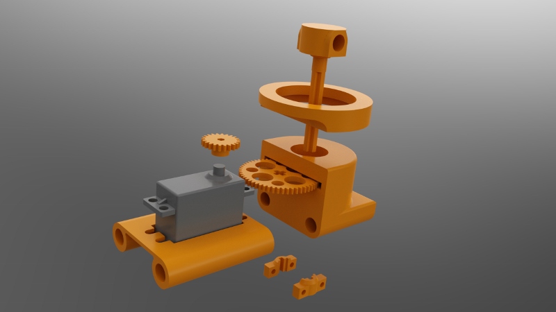
3. Core
Attach the GWS S125 1T servo to the servo bracket. The end of the servo with the shaft must go to the end of the servo bracket that is built up underneath. Use four M3x14mm bolts with M3 washers next to the bolt heads.
Press the servo gear onto the shaft of the servo. It will be a tight fit. Note that there are three servo gears. Use the “core” servo gear.
Press a 608ZZ bearing into the recesses in the top and bottom of the gear housing.
Slide the main gear into the slot in the gear housing.
Press the hub into the gear housing so that it goes through the upper 608ZZ bearing, the main gear and then the lower 608ZZ bearing. Make sure it is all the way in. It will be a tight fit. If you can’t make it fit through the gear then carefully file the hole in the gear, but do not overfile.
Attach the hub retainers to the bottom of the hub. These clamp onto the cross-shaped part of the hub. Use two M3x16mm bolts with nuts. It should be close to the bottom of the gear housing without touching it.
Place the support ring on top of the gear housing.
Slide two M8x200mm threaded rods through the left corner, servo bracket, gear housing and right corner. The order should be (from left to right):
M8 nut, M8 lock washer, left corner, servo bracket, gear housing, M8 lock washer, M8 nut, M8 nut, M8 lock washer, right corner, M8 lock washer, M8 nut.
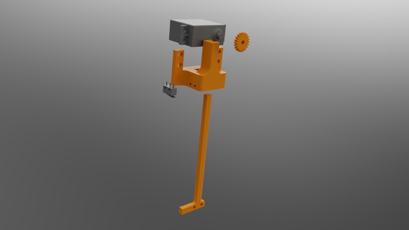
4. YAxis
Press the servo gear onto the Futaba S3003 servo (modified for continuous rotation). The fit will be tight. Be sure to use the servo gear for the Y axis.
Slide the servo down into the Y axis. The tabs on the servo go towards the front of the Y axis.
Push the rod up into the Y axis from the bottom. When it reaches the servo gear you will have to move the servo up and down a bit to get the rod to slide in. You can also carefully turn the servo by hand.
Attach the servo to the Y axis using four M3x14mm bolts. Use M3 washers next to the bold heads.
Attach the microswitch without a roller to the side of the Y axis using M2x14mm bolts. Put M2 nuts into the nut traps. Use the image above to orientate the microswitch.
Attach the Y axis to the core using a M8x220mm threader rod. A M8 nut goes into the nut trap on the underneath of the Y axis. The order should be (from front to back):
M8 nut (in nut trap), Y axis, M8 lock nut, M8 nut, M8 nut, M8 lock nut, hub, M8 lock nut, M8 nut
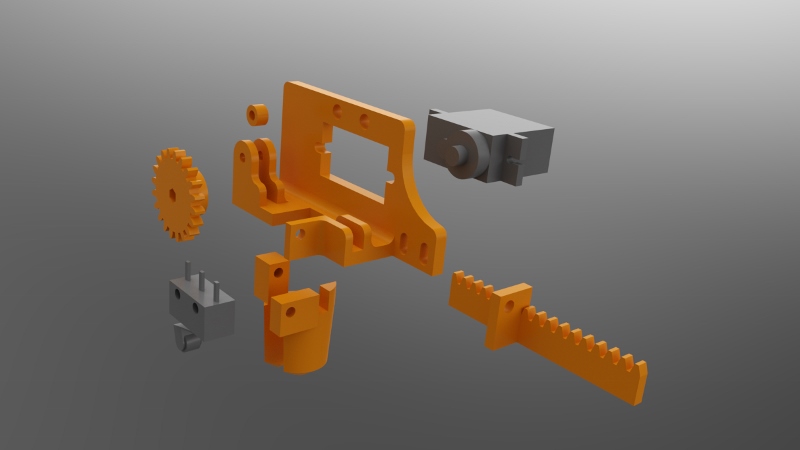
5. Toolhead
Screw the 9g micro servo to the back of the frame using two M2x10mm bolts.
Attach the guide which goes between the two forks using a single M2x10mm bolt.
Slide the rack into position.
Press the servo gear onto the servo shaft. It will be a tight fit. The teeth on the gear should mesh with the teeth on the rack.
Attach the fixed gripper to the frame using a M2x10mm bolt.
Attach the moving gripper to the rack using a M2x10mm bolt.
Attach the microswitch with the roller to the frame using two M2x10mm bolts.
Attach the toolhead to the bottom of the rod on the Y axis using two M3x14mm bolts.

Jack the Ripper Bot I – Introduction
Sep 3rd
I had a problem.
Over the last 15 years my wife has amassed a huge DVD collection and we don’t have enough space for shelving to access them all. About a year and a half ago I decided to start ripping the discs to a media server. This went well initially but it was tedious. Ripping is a slow business and every hour I had to feed the computer another disc which was disruptive to normal life. I gave up.
Recently inspired and armed with a 3D printer I decided to build a robot to perform the disc changing. Jack the Ripper Bot was born.
View the video of the robot in action: http://www.youtube.com/watch?v=mmHycIOtYHA
I will divide the description of Jack into five parts: introduction, mechanics, electronics, software and troubleshooting.
My aims were:
- Modular software and hardware design
- Open source
- Reliable
- Low cost
- Using off-the-shelf electronics
A stack of discs are placed into the “in tray”. An arm moves over to the stack and grabs the top disc. The disc is then lowered into the drive tray. Ripping takes place. Once complete the disc is removed from the drive tray and the arm takes it over to the “out tray” and places it there.
A Raspberry Pi is used to control the robot and a PC is used to control the overall process and the ripping.
I have a laptop which is about four years old and it can rip a DVD in about 1 hour 15 minutes. The in tray is designed to hold 24 discs to give about 28 hours of ripping time. It is of course possible to increase the capacity of the in tray and the out tray if your PC is faster than mine.
A complete bill of materials can be downloaded.
All files, including the software and part source files and STLs can be found on github. The files are licensed under GPLv3.
Pronsole Tips and Tricks
Jul 28th
Pronsole is a great way to control a 3D printer. it’s quick, efficient and customizable, however it does omit some useful commands. Here are some you can add to make it a bit more useful. Define the command using ‘macro’. then use the command by typing it’s name in.
motorsoff
This command turns the motors off. Useful if you wish to manually move an axis on the machine.
macro motorsoff M18
resetsd
On the Melzi board removing and inserting the SD card stops the card from being used any further until M21 is issued.
macro resetsd M21
loud
It can be handy to see all the gcodes that are being sent to the controller board and all the responses coming back. Also if you have a RepRapPro machine it won’t monitor the temperatures because pronsole doesn’t understand the values that are returned. Using this command will allow monitor to work again.
macro loud !self.p.loud = 1
quiet
This is the opposite of loud. It turns off reporting of gcodes and responses.
macro quiet !self.p.loud = 0

Rendering 3D Models
Jun 23rd
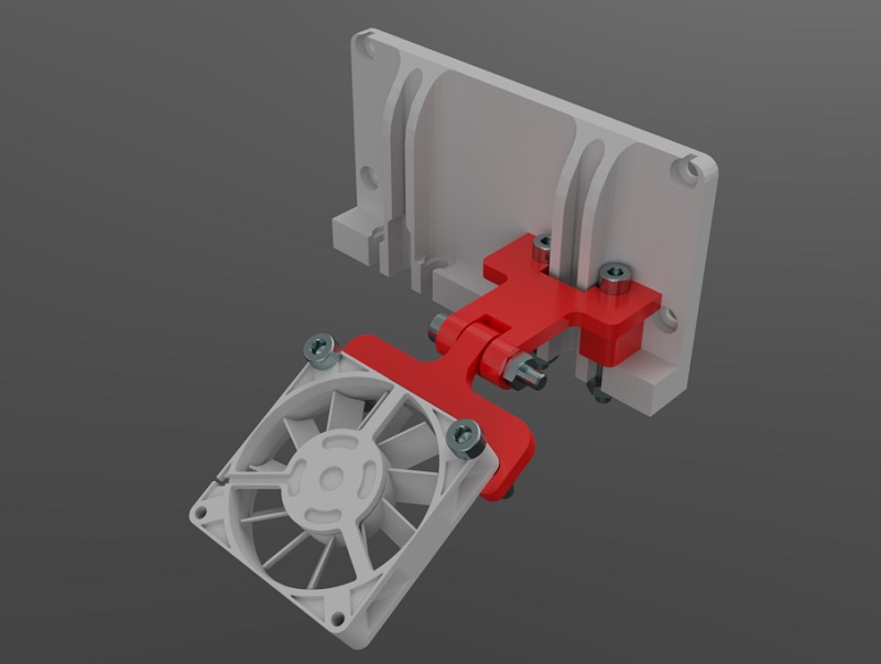
Rendering models using a variety of materials allows a finished object to be viewed and analyzed before committing to cutting wood or printing plastic. SimLab Composer works very well with Alibre Design. Here is an example showing my fan mount for the current RepRapPro Mendel design:
The nozzle mount is an STL from RepRapPro. The fan is an IGES file from GrabCAD. The M3 nuts and bolts are STLs from TraceParts. Finally the fan mount was exported as 3D PDF from Alibre Design.

Involute Gears in Alibre Design
Apr 25th
The most common type of gear is the involute gear, which provides smooth and efficient operation. A gear is defined by the following parameters:
- Pitch diameter (diameter of gear)
- Diametral pitch (tooth size)
- Number of teeth
- Pressure angle (commonly 14.5, 20 or 25 degrees)
The pressure angle defines the shape of a tooth. For two gears to mesh the pressure angle and diametral pitch must be the same (i.e. the shape and size of the teeth must match). There is a simple relationship between pitch diameter, diametral pitch and number of teeth so when defining a gear we only need to specify two of those parameters.
The ability to create involute gears is included in python-based ADScript. Let’s see how.
NumberofTeeth = 20
PitchDiameter = 30
PressureAngle = 20

InputGear = Part("Input Gear")
XYPlane = InputGear.GetPlane("XY-Plane")
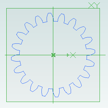
GearSketch = InputGear.AddGearNP("Gear Profile", NumberofTeeth, PitchDiameter, PressureAngle, 0, 0, XYPlane)
This script creates a new part called Input Gear and then adds a sketch to it on the XY-plane for the profile of a gear by calling AddGearNP. NP shows which two parameters are used, N = number of teeth and P = pitch diameter.
The 0, 0 defines the coordinates of the center of the gear.
Once the gear has been created we can read out the diametral pitch:
DiametralPitch = GearSketch.DiametralPitch
There are two other functions that we can call to create gears, depending on which two parameters we wish to use.
GearSketch1 = MyPart.AddGearDN("Gear Profile", DiametralPitch, NumberofTeeth, PressureAngle, 0, 0, XYPlane)
PitchDiameter = GearSketch1.PitchDiameter

GearSketch2 = MyPart.AddGearDP("Gear Profile", DiametralPitch, PitchDiameter, PressureAngle, 0, 0, XYPlane)
NumberofTeeth = GearSketch2.NumberofTeeth
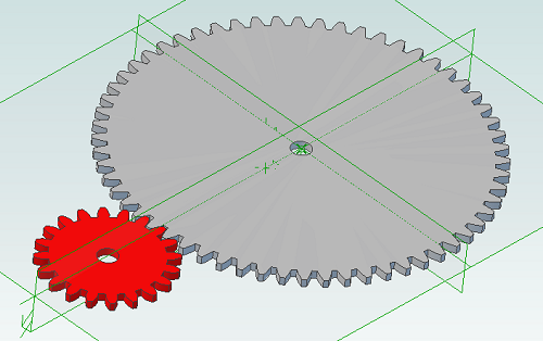
Here is an example script that shows how we can create two gears that can be used together to provide a 3:1 reduction ratio:
# all values are in millimeters
Units.Current = UnitTypes.Millimeters

# pressure angle has to be the same for both gears
# common values are 14.5, 20 and 25
# larger pressure angle = stronger teeth
PressureAngle = 20

# thickness of gears
Thickness = 2
# shaft diameter
ShaftDiameter = 5

# define input gear - 20 teeth and 30mm pitch diameter
Gear1Teeth = 20
Gear1Diameter = 30

# create input gear using number of teeth and pitch diameter
Gear1Part = Part("Input Gear")
Gear1 = Gear1Part.AddGearNP("Gear Profile", Gear1Teeth, Gear1Diameter, PressureAngle, 0, 0, Gear1Part.GetPlane("XY-Plane"))
Gear1.AddCircle(0, 0, ShaftDiameter, False)
Gear1Part.AddExtrudeBoss("Gear", Gear1, Thickness, False)

# diametral pitch must be the same for both gears as this defines tooth size
# use diametral pitch for output gear from input gear calculated value
Gear2DiametralPitch = Gear1.DiametralPitch

# we want a ratio of 1:3 so output gear has three times the number of teeth
Gear2Teeth = Gear1Teeth * 3

# create output gear using number of teeth and diametral pitch
Gear2Part = Part("Output Gear")
Gear2 = Gear2Part.AddGearDN("Gear Profile", Gear2DiametralPitch, Gear2Teeth, PressureAngle, 0, 0, Gear2Part.GetPlane("XY-Plane"))
Gear2.AddCircle(0, 0, ShaftDiameter, False)
Gear2Part.AddExtrudeBoss("Gear", Gear2, Thickness, False)

# get the calculated pitch diameter of the output gear
Gear2Diameter = Gear2.PitchDiameter

# calculate distance between gear centers so we know how far apart the shafts need to be
print "Distance between gear centers = %fmm\n" % ((Gear1Diameter + Gear2Diameter) / 2)
And the result:

Scripting Metric Screws in Alibre Design
Apr 10th
Creating screws is tedious. There are lots of diameter and length combinations and there is more to a screw than first meets the eye. Creating a parts library containing lots of variations is a perfect use for ADScript.
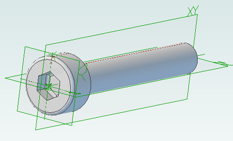
Here is a M3 x 20mm socket cap screw generated from the script below.
This screw is modeled to the ISO 4762 standard. Notice the threads are missing? Modeling the threads is generally a waste of time and resources as the aim is to ensure a screw fits, is long enough and there is enough clearance to install it.
# Creates a metric socket cap screw using ISO 4762
# See: http://practicalmaintenance.wordpress.com/2009/01/30/socket-head-cap-screws-article-13/

# Size of screw
Diameter = 3.0
Length = 20.0

# Measurements table containing H, F, E, T, C from web page
MetricData = {}
MetricData[1.6]  = [3.14,  2.0,  1.73,  0.7,  0.16]
MetricData[2.0]  = [3.98,  2.6,  1.73,  1.0,  0.2]
MetricData[2.5]  = [4.68,  3.1,  2.3,   1.1,  0.25]
MetricData[3.0]  = [5.68,  3.6,  2.87,  1.3,  0.3]
MetricData[4.0]  = [7.22,  4.7,  3.44,  2.0,  0.4]
MetricData[5.0]  = [8.72,  5.7,  4.58,  2.5,  0.5]
MetricData[6.0]  = [10.22, 6.8,  5.72,  3.0,  0.6]
MetricData[8.0]  = [13.27, 9.2,  6.86,  4.0,  0.8]
MetricData[10.0] = [16.27, 11.2, 9.15,  5.0,  1.0]
MetricData[12.0] = [18.27, 13.7, 11.43, 6.0,  1.2]
MetricData[16.0] = [24.33, 17.7, 16.0,  8.0,  1.6]
MetricData[20.0] = [30.33, 22.4, 19.44, 10.0, 2.0]
MetricData[24.0] = [36.39, 26.4, 21.73, 12.0, 2.4]
MetricData[30.0] = [45.39, 33.4, 25.15, 15.5, 3.0]
MetricData[36.0] = [54.46, 39.4, 30.85, 19.0, 3.6]
MetricData[42.0] = [63.46, 45.6, 36.57, 24.0, 4.2]
MetricData[48.0] = [72.46, 52.6, 41.13, 28.0, 4.8]
MetricData[56.0] = [84.54, 63.0, 46.83, 34.0, 5.6]
MetricData[64.0] = [96.54, 71.0, 52.53, 38.0, 6.4]

CapDiameter = MetricData[Diameter][0]
FilletTransitionDiameter = MetricData[Diameter][1]
HexHoleDiameter = MetricData[Diameter][2]
HexHoleDepth = MetricData[Diameter][3]
RimFilletRadius = MetricData[Diameter][4]

# all values are in millimeters
Units.Current = UnitTypes.Millimeters

# Create part
Screw = Part("Cap Screw M%dx%d" % (Diameter, Length))

# body
Profile = Screw.AddSketch("Profile", Screw.GetPlane("XY-Plane"))
Profile.AddLines([0, 0, 0, CapDiameter / 2, Diameter, CapDiameter / 2, Diameter, Diameter / 2, Diameter + Length, Diameter / 2, Diameter + Length, 0, 0, 0], False)
Screw.AddRevolveBoss("Body", Profile, Screw.GetAxis("X-Axis"), 360)

# hex hole
HexHole = Screw.AddSketch("Hole", Screw.GetFace("Face<5>"))
HexHole.AddPolygon(0, 0, HexHoleDiameter, 6, False)
Screw.AddExtrudeCut("Hex Hole", HexHole, HexHoleDepth + ((FilletTransitionDiameter - Diameter) / 2.0), True)

# fillet from cap to shaft
Screw.AddFillet("Cap Joint", Screw.GetEdge("Edge<21>"), (FilletTransitionDiameter - Diameter) / 2.0, False)
# fillet at bottom of hex hole
Screw.AddFillet("Hex Hole Bottom", [Screw.GetEdge("Edge<5>"), Screw.GetEdge("Edge<9>"), Screw.GetEdge("Edge<12>"), Screw.GetEdge("Edge<21>"), Screw.GetEdge("Edge<18>"), Screw.GetEdge("Edge<15>")], (FilletTransitionDiameter - Diameter) / 2.0, False)
# fillet on rim
Screw.AddFillet("Cap Rim", Screw.GetEdge("Edge<35>"), RimFilletRadius, False)
