Interesting Tech Projects
Jack the Ripper Bot III – Electronics
Part 1 covered the introduction and part 2 the mechanics. Here is part 3 that shows the electronics side.
The following block diagram shows the arrangement of the electronics.
For wifi connect a USB wifi interface to the Raspberry Pi (RPi). Connect a USB cable from the RPi to the Maestro. I connect to the RPi via SSH and I have configured my router to always assign the same IP address.
The Maestro requires a separate 5V power supply for the servos.
Connect the servos to the Maestro as follows:
- Channel 0 = Core servo for pivoting
- Channel 1 = Y axis servo
- Channel 2 = Toolhead servo
Use the servo extension cables for the Y axis and toolhead servo.
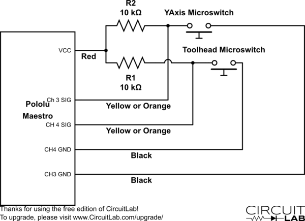
Wire the microswitches as shown in this diagram. I used servo extension cables and the colors mentioned reflect that. Note that the signal wire could also be white.
The 5V connection to the Maestro is not the one on the servo connectors. There is a separate 5V and GND along the top edge. See this section of the Maestro user’s guide for details.
Solder a two pin header onto the pads for the 5V and GND. Use the two way molex connector and 0.1 inch pins to create a connector to plug onto the header. Note that the ground pin is not used, instead the ground on the servo connectors is used.
| Print article | This entry was posted by Andy on September 5, 2013 at 12:00 pm, and is filed under 3D Printing, Computer Aided Design. Follow any responses to this post through RSS 2.0. Both comments and pings are currently closed. |
Comments are closed.


about 9 years ago
I don’t understand the section under the circuit diagram very well.
Could you post an image of what the setup looks like? Did you use a molex connector to allow the pololu to be disconnected from the switches?
about 9 years ago
The servos connect as usual. The power supply comes from USB to the 5V/GND solder pads, where you need to add a header and connector. The key point is that the Pololu has it’s own power supply so if the servos draw a lot of current it doesn’t affect the Raspberry Pi.
about 9 years ago
Ok, so that part is just clarifying that the Vcc in the diagram is coming for the Pololu. The rest is just a convenience thing to allow quick disconnect, right?
Also, when you say molex connector, do you mean the one on the left, or the one on the right?
http://common.ziffdavisinternet.com/encyclopedia_images/_PSCONN.JPG
about 9 years ago
All connectors on the Pololu are 0.1″ pitch.
about 8 years ago
I don’t know if I just messed something up but my Y axis servo only turns one direction and just keeps on turning once I turn it on in the Maestro software. Did I mess it up somehow?
about 8 years ago
If I recall correctly if the pulse width is in the “center” then it stops rotating. If the pulse width is slightly less than “center” then it goes in one direction and if it is slightly more than “center” it goes in the other direction.
about 8 years ago
Andy, thanks for the input on the continuous servo issue. I’ve got the servos all working but am unsure of how exactly to wire up the micro-switches. How many connections to the Maestro do you make? I’m terrible about reading circuit diagrams but the way I’m reading the diagram above is as follows:
For each switch make a connection to the 5v VCC pin with a resistor inline which wires to the signal wire for the switch and both connect to the terminal of the switch that is not connect to the common. Then a wire is connected to the channel’s ground pin such that when the switch is triggered the 5V connects to the ground and draws the voltage down.
Is this correct or have I completely misunderstood the diagram?