Interesting Tech Projects
Jack the Ripper Bot II – Mechanics
Part I covered the introduction to the robot. This part covers the mechanical assembly.
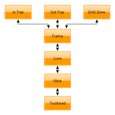
I divided the mechanical design into several groups, which I will refer to throughout. These names are also used for the part designs.
The frame holds everything together. It attaches to the DVD drive. Onto the frame is the in and out trays and what I call the “core”. The core is the main pivoting mechanism for the arm that loads and unloads discs.
At the end of the arm is the YAxis which raises and lowers discs. This should have been called the ZAxis but C’est la vie…
Finally the toolhead is at the bottom of the YAxis and grabs and releases discs.
General Notes
I printed all parts in PLA with three perimeters and 20% fill.
No support is required. The STLs are already correctly orientated.
Any STL name ending in _X2.stl means print two copies of that part.
Whereever M8 nuts are used always use a M8 lock washer against the nut, unless the nut goes into a nut trap.
Exploded diagrams don’t show M8 lock washers, M3 hardware or M2 hardware.
Filing of the printed parts may be needed, especially for the M2 nut traps and if the first layer has a lip because it was squashed.
If you are unsure about any step you can download a 3D PDF of the entire robot. Open in Adobe Reader and click on the image. You can then spin the model around and zoom in to examine it from every angle.
1. DVD Drive
The DVD drive must be an internal 5.25 inch type designed to be used horizontally. The tray electronics must open and close the tray fully by pressing the front button on the drive. When the tray is open it must be possible to lower a disc into the tray vertically. I.e. make sure the front of the drive does not overhang the back of the tray slightly.
2. Frame
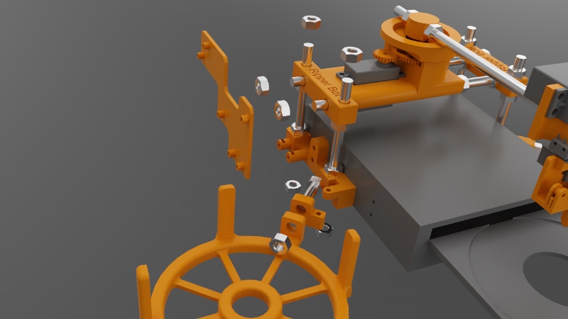
Attach the left and right brackets onto the drive using M3x12 bolts and the rear mounting holes in the drive case. The curved ends go towards the rear.
Attach the tray anchors to the left and right brackets using M3x18mm bolts. M3 nuts go into the recesses on the bottom of the tray anchors.
Attach the in and out trays to the tray anchors. Use M8x30mm threaded rod, M8 nuts and M8 lock washers. The out tray has slightly sloping sides at the top. The in tray does not.
Attach the electronics caddy to the left bracket using two M3x14mm bolts. Put M3 nuts into the nut traps.
Attach the four M3x100mm threaded rods to the left and right brackets. M8 nuts are placed into the recesses in the bottom of the brackets.
Attach the corners to the threaded rods you just added. They should be positioned as close as possible to the top of the threaded rods.
3. Core
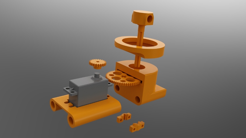
Attach the GWS S125 1T servo to the servo bracket. The end of the servo with the shaft must go to the end of the servo bracket that is built up underneath. Use four M3x14mm bolts with M3 washers next to the bolt heads.
Press the servo gear onto the shaft of the servo. It will be a tight fit. Note that there are three servo gears. Use the “core” servo gear.
Press a 608ZZ bearing into the recesses in the top and bottom of the gear housing.
Slide the main gear into the slot in the gear housing.
Press the hub into the gear housing so that it goes through the upper 608ZZ bearing, the main gear and then the lower 608ZZ bearing. Make sure it is all the way in. It will be a tight fit. If you can’t make it fit through the gear then carefully file the hole in the gear, but do not overfile.
Attach the hub retainers to the bottom of the hub. These clamp onto the cross-shaped part of the hub. Use two M3x16mm bolts with nuts. It should be close to the bottom of the gear housing without touching it.
Place the support ring on top of the gear housing.
Slide two M8x200mm threaded rods through the left corner, servo bracket, gear housing and right corner. The order should be (from left to right):
M8 nut, M8 lock washer, left corner, servo bracket, gear housing, M8 lock washer, M8 nut, M8 nut, M8 lock washer, right corner, M8 lock washer, M8 nut.
4. YAxis
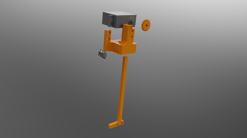
Press the servo gear onto the Futaba S3003 servo (modified for continuous rotation). The fit will be tight. Be sure to use the servo gear for the Y axis.
Slide the servo down into the Y axis. The tabs on the servo go towards the front of the Y axis.
Push the rod up into the Y axis from the bottom. When it reaches the servo gear you will have to move the servo up and down a bit to get the rod to slide in. You can also carefully turn the servo by hand.
Attach the servo to the Y axis using four M3x14mm bolts. Use M3 washers next to the bold heads.
Attach the microswitch without a roller to the side of the Y axis using M2x14mm bolts. Put M2 nuts into the nut traps. Use the image above to orientate the microswitch.
Attach the Y axis to the core using a M8x220mm threader rod. A M8 nut goes into the nut trap on the underneath of the Y axis. The order should be (from front to back):
M8 nut (in nut trap), Y axis, M8 lock nut, M8 nut, M8 nut, M8 lock nut, hub, M8 lock nut, M8 nut
5. Toolhead
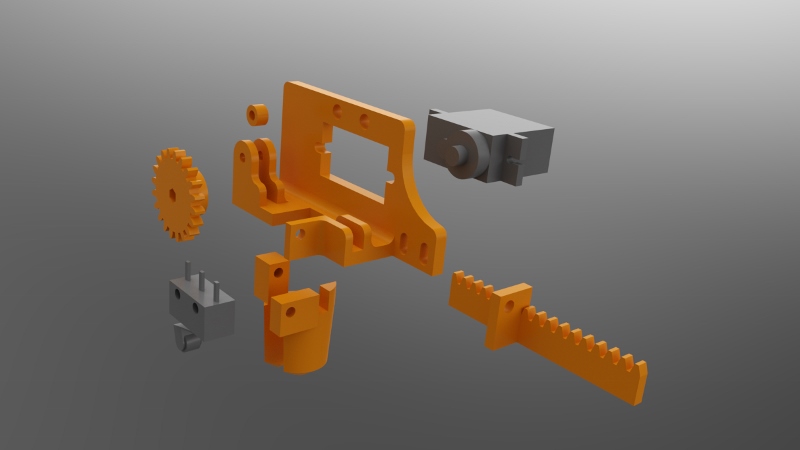
Screw the 9g micro servo to the back of the frame using two M2x10mm bolts.
Attach the guide which goes between the two forks using a single M2x10mm bolt.
Slide the rack into position.
Press the servo gear onto the servo shaft. It will be a tight fit. The teeth on the gear should mesh with the teeth on the rack.
Attach the fixed gripper to the frame using a M2x10mm bolt.
Attach the moving gripper to the rack using a M2x10mm bolt.
Attach the microswitch with the roller to the frame using two M2x10mm bolts.
Attach the toolhead to the bottom of the rod on the Y axis using two M3x14mm bolts.
| Print article | This entry was posted by Andy on September 4, 2013 at 12:00 pm, and is filed under 3D Printing, Computer Aided Design. Follow any responses to this post through RSS 2.0. Both comments and pings are currently closed. |
Comments are closed.


about 11 years ago
great idea and fantastic build, yet another thing to add to my list of things to build, man there is not enough hours in the day!!!
about 11 years ago
I have the exact same problem! I originally solved the problem by moving all my DVDs into CD wallets… however now I have dozens of CD wallets, and have well over 2,000 DVDs (excluding boxsets).
I don’t suppose you’re planning on selling the parts for these by chance?
about 11 years ago
Unfortunately I don’t have time to make and sell parts. You can upload the STL files to 3D printing companies that can make them for you, such as iMaterialise. I hope that helps.
about 8 years ago
Hello, do you have a guide for continuous rotation modification of the Futaba S3003 servo?
about 8 years ago
You just need to disassemble it and remove the small tab that blocks rotation. You should be able to find steps and pictures on sites like Instructables.
about 5 years ago
You write
“Attach the Y axis to the core using a M8x220mm threader rod. A M8 nut goes into the nut trap on the underneath of the Y axis. The order should be (from front to back):
M8 nut (in nut trap), Y axis, M8 lock nut, M8 nut, M8 nut, M8 lock nut, hub, M8 lock nut, M8 nut”
do you mean using a m8 washer or really a lock nut? I think a lock nut cant have the rod coming out on both sides, thats why its called a lock nut.
about 5 years ago
I can’t recall sorry – it’s been too long.