Interesting Tech Projects
Involute Gears in Alibre Design
The most common type of gear is the involute gear, which provides smooth and efficient operation. A gear is defined by the following parameters:
- Pitch diameter (diameter of gear)
- Diametral pitch (tooth size)
- Number of teeth
- Pressure angle (commonly 14.5, 20 or 25 degrees)
The pressure angle defines the shape of a tooth. For two gears to mesh the pressure angle and diametral pitch must be the same (i.e. the shape and size of the teeth must match). There is a simple relationship between pitch diameter, diametral pitch and number of teeth so when defining a gear we only need to specify two of those parameters.
The ability to create involute gears is included in python-based ADScript. Let’s see how.
NumberofTeeth = 20
PitchDiameter = 30
PressureAngle = 20

InputGear = Part("Input Gear")
XYPlane = InputGear.GetPlane("XY-Plane")
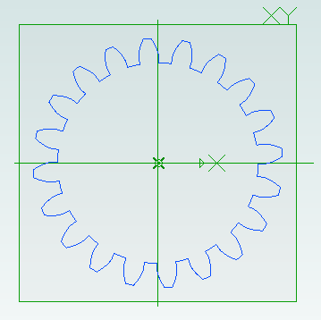
GearSketch = InputGear.AddGearNP("Gear Profile", NumberofTeeth, PitchDiameter, PressureAngle, 0, 0, XYPlane)
This script creates a new part called Input Gear and then adds a sketch to it on the XY-plane for the profile of a gear by calling AddGearNP. NP shows which two parameters are used, N = number of teeth and P = pitch diameter.
The 0, 0 defines the coordinates of the center of the gear.
Once the gear has been created we can read out the diametral pitch:
DiametralPitch = GearSketch.DiametralPitch
There are two other functions that we can call to create gears, depending on which two parameters we wish to use.
GearSketch1 = MyPart.AddGearDN("Gear Profile", DiametralPitch, NumberofTeeth, PressureAngle, 0, 0, XYPlane)
PitchDiameter = GearSketch1.PitchDiameter

GearSketch2 = MyPart.AddGearDP("Gear Profile", DiametralPitch, PitchDiameter, PressureAngle, 0, 0, XYPlane)
NumberofTeeth = GearSketch2.NumberofTeeth
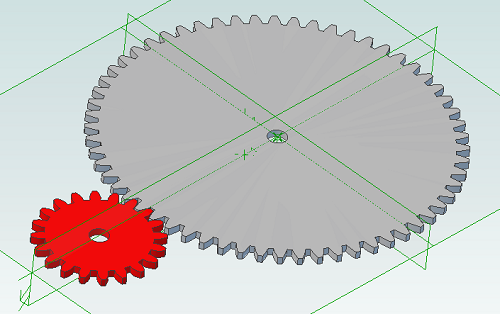
Here is an example script that shows how we can create two gears that can be used together to provide a 3:1 reduction ratio:
# all values are in millimeters
Units.Current = UnitTypes.Millimeters

# pressure angle has to be the same for both gears
# common values are 14.5, 20 and 25
# larger pressure angle = stronger teeth
PressureAngle = 20

# thickness of gears
Thickness = 2
# shaft diameter
ShaftDiameter = 5

# define input gear - 20 teeth and 30mm pitch diameter
Gear1Teeth = 20
Gear1Diameter = 30

# create input gear using number of teeth and pitch diameter
Gear1Part = Part("Input Gear")
Gear1 = Gear1Part.AddGearNP("Gear Profile", Gear1Teeth, Gear1Diameter, PressureAngle, 0, 0, Gear1Part.GetPlane("XY-Plane"))
Gear1.AddCircle(0, 0, ShaftDiameter, False)
Gear1Part.AddExtrudeBoss("Gear", Gear1, Thickness, False)

# diametral pitch must be the same for both gears as this defines tooth size
# use diametral pitch for output gear from input gear calculated value
Gear2DiametralPitch = Gear1.DiametralPitch

# we want a ratio of 1:3 so output gear has three times the number of teeth
Gear2Teeth = Gear1Teeth * 3

# create output gear using number of teeth and diametral pitch
Gear2Part = Part("Output Gear")
Gear2 = Gear2Part.AddGearDN("Gear Profile", Gear2DiametralPitch, Gear2Teeth, PressureAngle, 0, 0, Gear2Part.GetPlane("XY-Plane"))
Gear2.AddCircle(0, 0, ShaftDiameter, False)
Gear2Part.AddExtrudeBoss("Gear", Gear2, Thickness, False)

# get the calculated pitch diameter of the output gear
Gear2Diameter = Gear2.PitchDiameter

# calculate distance between gear centers so we know how far apart the shafts need to be
print "Distance between gear centers = %fmm\n" % ((Gear1Diameter + Gear2Diameter) / 2)
And the result:
| Print article | This entry was posted by Andy on April 25, 2013 at 11:26 am, and is filed under Computer Aided Design, Software Engineering. Follow any responses to this post through RSS 2.0. Both comments and pings are currently closed. |
Comments are closed.

