Interesting Tech Projects
Archive for April, 2013

Involute Gears in Alibre Design
Apr 25th
The most common type of gear is the involute gear, which provides smooth and efficient operation. A gear is defined by the following parameters:
- Pitch diameter (diameter of gear)
- Diametral pitch (tooth size)
- Number of teeth
- Pressure angle (commonly 14.5, 20 or 25 degrees)
The pressure angle defines the shape of a tooth. For two gears to mesh the pressure angle and diametral pitch must be the same (i.e. the shape and size of the teeth must match). There is a simple relationship between pitch diameter, diametral pitch and number of teeth so when defining a gear we only need to specify two of those parameters.
The ability to create involute gears is included in python-based ADScript. Let’s see how.
NumberofTeeth = 20
PitchDiameter = 30
PressureAngle = 20

InputGear = Part("Input Gear")
XYPlane = InputGear.GetPlane("XY-Plane")
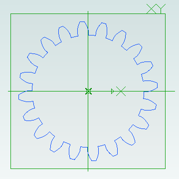
GearSketch = InputGear.AddGearNP("Gear Profile", NumberofTeeth, PitchDiameter, PressureAngle, 0, 0, XYPlane)
This script creates a new part called Input Gear and then adds a sketch to it on the XY-plane for the profile of a gear by calling AddGearNP. NP shows which two parameters are used, N = number of teeth and P = pitch diameter.
The 0, 0 defines the coordinates of the center of the gear.
Once the gear has been created we can read out the diametral pitch:
DiametralPitch = GearSketch.DiametralPitch
There are two other functions that we can call to create gears, depending on which two parameters we wish to use.
GearSketch1 = MyPart.AddGearDN("Gear Profile", DiametralPitch, NumberofTeeth, PressureAngle, 0, 0, XYPlane)
PitchDiameter = GearSketch1.PitchDiameter

GearSketch2 = MyPart.AddGearDP("Gear Profile", DiametralPitch, PitchDiameter, PressureAngle, 0, 0, XYPlane)
NumberofTeeth = GearSketch2.NumberofTeeth
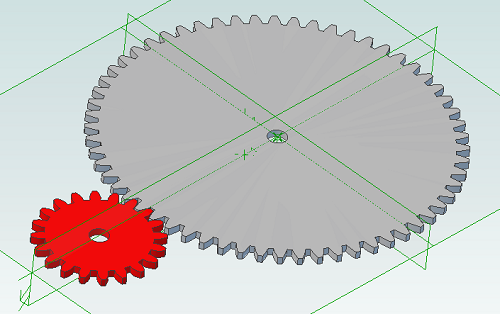
Here is an example script that shows how we can create two gears that can be used together to provide a 3:1 reduction ratio:
# all values are in millimeters
Units.Current = UnitTypes.Millimeters

# pressure angle has to be the same for both gears
# common values are 14.5, 20 and 25
# larger pressure angle = stronger teeth
PressureAngle = 20

# thickness of gears
Thickness = 2
# shaft diameter
ShaftDiameter = 5

# define input gear - 20 teeth and 30mm pitch diameter
Gear1Teeth = 20
Gear1Diameter = 30

# create input gear using number of teeth and pitch diameter
Gear1Part = Part("Input Gear")
Gear1 = Gear1Part.AddGearNP("Gear Profile", Gear1Teeth, Gear1Diameter, PressureAngle, 0, 0, Gear1Part.GetPlane("XY-Plane"))
Gear1.AddCircle(0, 0, ShaftDiameter, False)
Gear1Part.AddExtrudeBoss("Gear", Gear1, Thickness, False)

# diametral pitch must be the same for both gears as this defines tooth size
# use diametral pitch for output gear from input gear calculated value
Gear2DiametralPitch = Gear1.DiametralPitch

# we want a ratio of 1:3 so output gear has three times the number of teeth
Gear2Teeth = Gear1Teeth * 3

# create output gear using number of teeth and diametral pitch
Gear2Part = Part("Output Gear")
Gear2 = Gear2Part.AddGearDN("Gear Profile", Gear2DiametralPitch, Gear2Teeth, PressureAngle, 0, 0, Gear2Part.GetPlane("XY-Plane"))
Gear2.AddCircle(0, 0, ShaftDiameter, False)
Gear2Part.AddExtrudeBoss("Gear", Gear2, Thickness, False)

# get the calculated pitch diameter of the output gear
Gear2Diameter = Gear2.PitchDiameter

# calculate distance between gear centers so we know how far apart the shafts need to be
print "Distance between gear centers = %fmm\n" % ((Gear1Diameter + Gear2Diameter) / 2)
And the result:

Scripting Metric Screws in Alibre Design
Apr 10th
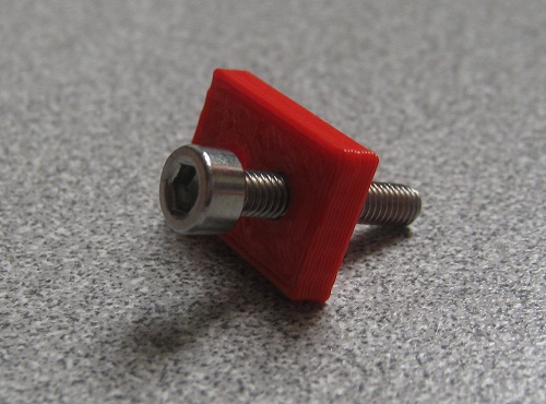
Creating screws is tedious. There are lots of diameter and length combinations and there is more to a screw than first meets the eye. Creating a parts library containing lots of variations is a perfect use for ADScript.
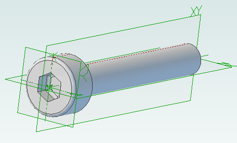
Here is a M3 x 20mm socket cap screw generated from the script below.
This screw is modeled to the ISO 4762 standard. Notice the threads are missing? Modeling the threads is generally a waste of time and resources as the aim is to ensure a screw fits, is long enough and there is enough clearance to install it.
# Creates a metric socket cap screw using ISO 4762
# See: http://practicalmaintenance.wordpress.com/2009/01/30/socket-head-cap-screws-article-13/

# Size of screw
Diameter = 3.0
Length = 20.0

# Measurements table containing H, F, E, T, C from web page
MetricData = {}
MetricData[1.6]  = [3.14,  2.0,  1.73,  0.7,  0.16]
MetricData[2.0]  = [3.98,  2.6,  1.73,  1.0,  0.2]
MetricData[2.5]  = [4.68,  3.1,  2.3,   1.1,  0.25]
MetricData[3.0]  = [5.68,  3.6,  2.87,  1.3,  0.3]
MetricData[4.0]  = [7.22,  4.7,  3.44,  2.0,  0.4]
MetricData[5.0]  = [8.72,  5.7,  4.58,  2.5,  0.5]
MetricData[6.0]  = [10.22, 6.8,  5.72,  3.0,  0.6]
MetricData[8.0]  = [13.27, 9.2,  6.86,  4.0,  0.8]
MetricData[10.0] = [16.27, 11.2, 9.15,  5.0,  1.0]
MetricData[12.0] = [18.27, 13.7, 11.43, 6.0,  1.2]
MetricData[16.0] = [24.33, 17.7, 16.0,  8.0,  1.6]
MetricData[20.0] = [30.33, 22.4, 19.44, 10.0, 2.0]
MetricData[24.0] = [36.39, 26.4, 21.73, 12.0, 2.4]
MetricData[30.0] = [45.39, 33.4, 25.15, 15.5, 3.0]
MetricData[36.0] = [54.46, 39.4, 30.85, 19.0, 3.6]
MetricData[42.0] = [63.46, 45.6, 36.57, 24.0, 4.2]
MetricData[48.0] = [72.46, 52.6, 41.13, 28.0, 4.8]
MetricData[56.0] = [84.54, 63.0, 46.83, 34.0, 5.6]
MetricData[64.0] = [96.54, 71.0, 52.53, 38.0, 6.4]

CapDiameter = MetricData[Diameter][0]
FilletTransitionDiameter = MetricData[Diameter][1]
HexHoleDiameter = MetricData[Diameter][2]
HexHoleDepth = MetricData[Diameter][3]
RimFilletRadius = MetricData[Diameter][4]

# all values are in millimeters
Units.Current = UnitTypes.Millimeters

# Create part
Screw = Part("Cap Screw M%dx%d" % (Diameter, Length))

# body
Profile = Screw.AddSketch("Profile", Screw.GetPlane("XY-Plane"))
Profile.AddLines([0, 0, 0, CapDiameter / 2, Diameter, CapDiameter / 2, Diameter, Diameter / 2, Diameter + Length, Diameter / 2, Diameter + Length, 0, 0, 0], False)
Screw.AddRevolveBoss("Body", Profile, Screw.GetAxis("X-Axis"), 360)

# hex hole
HexHole = Screw.AddSketch("Hole", Screw.GetFace("Face<5>"))
HexHole.AddPolygon(0, 0, HexHoleDiameter, 6, False)
Screw.AddExtrudeCut("Hex Hole", HexHole, HexHoleDepth + ((FilletTransitionDiameter - Diameter) / 2.0), True)

# fillet from cap to shaft
Screw.AddFillet("Cap Joint", Screw.GetEdge("Edge<21>"), (FilletTransitionDiameter - Diameter) / 2.0, False)
# fillet at bottom of hex hole
Screw.AddFillet("Hex Hole Bottom", [Screw.GetEdge("Edge<5>"), Screw.GetEdge("Edge<9>"), Screw.GetEdge("Edge<12>"), Screw.GetEdge("Edge<21>"), Screw.GetEdge("Edge<18>"), Screw.GetEdge("Edge<15>")], (FilletTransitionDiameter - Diameter) / 2.0, False)
# fillet on rim
Screw.AddFillet("Cap Rim", Screw.GetEdge("Edge<35>"), RimFilletRadius, False)

Scripting Polyholes in Alibre Design
Apr 6th
3D printing by using layers of melted plastic filament, such as used by RepRap printers, causes small holes (less than 15mm in diameter) to end up smaller than the designed size. To compensate for this people create designs with larger holes so they shrink to the right size. It’s not an ideal solution – how much do they need to be increased by? What if you later want to send the same design to a commercial printing service that is more accurate?
The RepRap developer Nophead examined this issue and came up with a simple way to design holes that print at the right size regardless of the printing method. He called them polyholes.
In short the solution is to approximate the hole with a polygon and increase it’s size slightly.
Creating these polyholes in a CAD package is tedious. The size has to be calculated and the number of sides varies with the hole size. ADScript has this functionality baked right in. Here is an example python script:
# use millimeters for all values
Units.Current = UnitTypes.Millimeters

# test block dimensions
length = 15
width = 10
depth = 3
# size of test holes
diameter = 3

# create a new part, get the XY plane and create a sketch on the plane
PolyholeTest = Part("PolyholeTest")
XYPlane = PolyholeTest.GetPlane("XY-Plane")
Base = PolyholeTest.AddSketch("Base", XYPlane)

# draw the part outline
Base.AddPolyline([0, 0, length, 0, length, width, 0, width, 0, 0], False)
# draw a regular hole
Base.AddCircle(length / 3, width / 2, diameter, False)
# draw a polyhole
Base.AddPolyhole(length / 3 * 2, width / 2, diameter, False)
# extrude the sketch into a part
PolyholeTest.AddExtrudeBoss("Block", Base, depth, False)

# save and export to STL for printing
PolyholeTest.Save("C:\Users\Andy\Desktop")
PolyholeTest.ExportSTL("C:\Users\Andy\Desktop\PolyholeTest.stl")
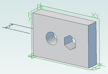
When this script is run it produces the following test part with the regular hole on the left and the polyhole on the right:
To rotate the part simply change the plane used, perhaps to “ZX-Plane”, and run the script again.

Python Scripting with Alibre Design
Apr 3rd
ADScript makes it easy to use Alibre Design with Python scripting. For example creating a new part:
Test = Part("Test")
We can get access to planes in the design workspace, for example:
XYPlane = Test.GetPlane("XY-Plane")
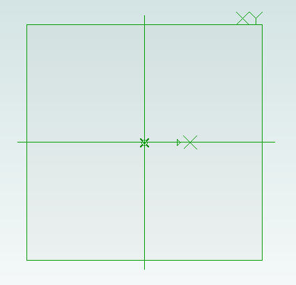
Once we have a part and plane we can create a sketch on the plane:
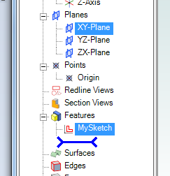
MySketch = Test.AddSketch("MySketch", XYPlane)
Adding to the sketch is easy:
MySketch.AddCircle(0, 0, 10, False)
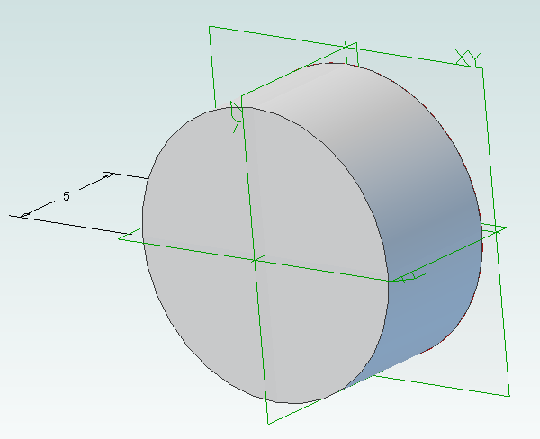
Now we can extrude it:
Object = Test.AddExtrudeBoss("Object", MySketch, 5, False)
