Interesting Tech Projects
Archive for March, 2013

Using Alibre Design for 3D Printing of Multi-Part Projects
Mar 13th
The easiest way to design projects that involve multiple parts in Alibre Design is to create and edit parts inside an assembly workspace. This allows the edges and cross-sections of one part to be reused in another part which is very useful.
However for 3D printing there is a downside – creating a part inside an assembly results in that part being orientated the same way in the part workspace as it in the assembly workspace. For 3D printing we want a specific side face down on the XY plane. That choice of side depends on the part.
So we have taken advantage of the tools and features that Alibre Design offers but we now have parts that are not orientated correctly for printing. They can be rotated in Alibre Design by creating a new assembly just for that part but there must be an easier way.
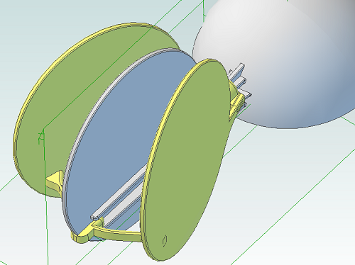
The following screenshot illustrates the problem. The circular panel is in an assembly and orientated the way we need it to check that everything fits together.
Opening the part in it’s own workspace shows the orientation.
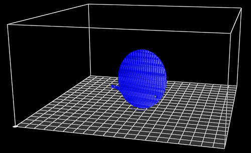
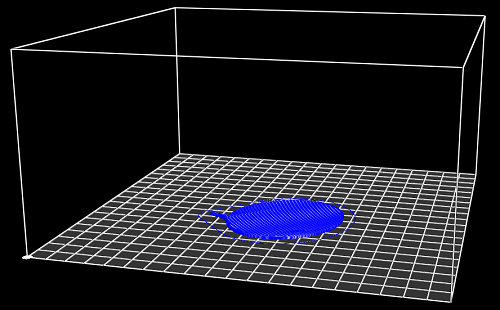
Exporting and slicing this part as it is results in the following g-code.
So how can we make this easier, especially if we have an assembly with lots of parts? By using an add-on for Alibre Design.
I’ve updated my AD Assembly Exporter utility that I have previously written about. It can now automatically rotate STLs when they are exported so that the desired face is aligned with the XY plane.
First you must choose the face that will be placed on the print bed.
- Edit the part
- Right-click on the face and choose Insert Plane..
.
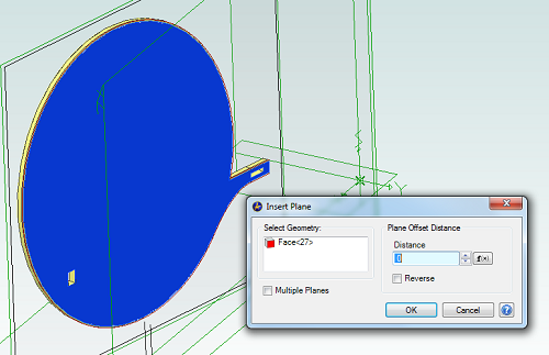
- Click on OK
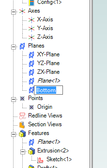
- In the Design Explorer right-click on the new plane and choose Rename
- Enter the name “Bottom”
Now save the part and open the assembly containing it, if it wasn’t already open. Repeat this for all parts in the assembly that will be printed.
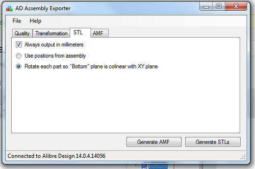
Run AD Assembly Exporter, click on the STL tab and choose the option to rotate using the “Bottom” plane.
Then click on Generate STLs. Here is the new g-code output:

Leveling a RepRap Bed with Three Screws
Mar 3rd
The majority of beds on RepRap 3D printers are leveled using four adjustment screws, one at each corner, and therefore most if not all leveling instructions are for that situation. The RepRapPro printers are different in that they have only three screws and there is little detailed information on how to use them to level the bed. Here are the steps I use.
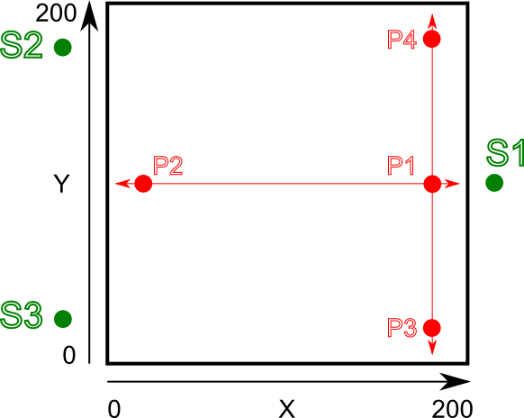
This is a view of the bed looking from above and standing at the front of the printer.
The home position of X = 0, Y = 0 is at the bottom left. Green dots indicate the positions of the adjustment screws for leveling the bed. Red dots indicate the measurement positions of the hotend (the nozzle). It is important to note that when at normal operating temperature the bed and hotend move closer together through expansion from the heat. Therefore leveling must be performed while hot.
- Set the bed to 60C and the hotend to 150C. I use a slightly lower temperature on the hotend to stop oozing of filament during the process. You can optionally retract or remove the filament if you prefer
- Loosen all three adjustment screws, S1, S2 and S3. I.e. the bed is raised to it’s maximum height while still being securely attached to the Y axis.
- Move the Z endstop thumbwheel to a conservative position so that when Z is homed the hotend won’t crash into the bed.
- Move hotend to position P1 (X = 200, Y = 100)
- Repeatedly adjust the Z endstop thumbwheel and home the Z axis until the hotend is the thickness of a piece of paper above the bed.
- Move hotend to position P2 (X = 0, Y = 100) and home Z
- We now need to adjust the height of the bed so that the hotend is the thickness of a piece of paper above the bed. The left side of the bed can be raised and lowered by adjusting screws S2 and S3 in parallel – i.e. turning them both in the same direction and by the same amount.
- At this point the hotend should now be perfectly aligned with the bed along the horizontal red line shown in the diagram. What we still don’t know is if the bed is tilted towards the front or back, which we will now check.
- Move the hotend to position P3 (X = 200, Y = 0) and home Z
- Adjust the height of the front right corner of the bed so that the hotend is the thickness of a piece of paper above the bed. This corner can be adjusted by using screw S2 only. For example, if we turn S2 clockwise we will lower the rear left corner which will raise the front right corner, moving it closer to the hotend.
- Move the hotend to position P4 (X = 200, Y = 200) and home Z
- Adjust the height of the rear right corner of the bed so that the hotend is the thickness of a piece of paper above the bed. This corner can be adjusted by using screw S3 only. For example, if we turn S3 clockwise we will lower the front left corner which will raise the rear right corner, moving it closer to the hotend.
- At this point the hotend should now be perfectly aligned with the bed along the vertical red line shown in the diagram. Alignment in two directions means that the entire bed should be level. The problem with the two previous adjustments is that they slightly affect other areas of the bed at the same time, which we don’t want. The way to minimize this is to now repeat the process again by going back to step 4.
- Finally double-check the height of the hotend above the bed at the center (X = 100, Y = 100). It should be the thickness of a piece of paper.
