Interesting Tech Projects
Measuring CNC Backlash and Software Compensation
This article describes how I measured the backlash on my CNC machine and then applied software compensation.
To measure backlash I used a Mitutoyo dial indicator with 0.0001″ markings and a full scale of 0.01″. The dial indicator was attached to an adjustable stand so the plunger could be placed against various surfaces on the machine. The stand had a heavy base to ensure the dial indicator and stand didn’t move when pressure was applied to the plunger.
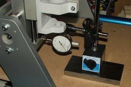
The picture below shows the set up ready to measure the backlash of the X axis.
Here is the method I used:
- Position the plunger on the dial indicator a short distance from a surface that moves in the direction of the axis being measured. The plunger should be perpendicular to the surface.
- Jog 0.001″ along the axis being measured into the plunger, until the needle moves at least 0.001″.
- Note the value shown on the dial indicator. We’ll call this ‘S’ for start.
- Jog the axis 0.001″ seven times into the plunger. Each jog will cause the needle to move. Be careful not to cause the needle to move to the maximum position.
- Jog the axis 0.001″ seven times away from the plunger. The first one, two or three jogs may not cause the needle to move. This is the slack being taken up and hence the backlash.
- Note the value shown on the dial indicator. We’ll call this ‘F’ for finish.
- Calculate the difference between the finish value and the start value (F -S). This is the amount of backlash.
- Jog the axis away from the plunger
- Repeat two more times then work out the average value.
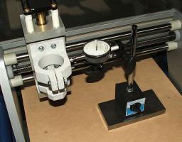
The next picture shows the position of the dial indicator used to measure the Y axis.
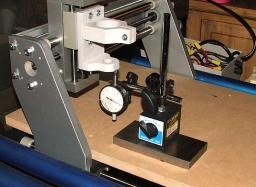
The last picture shows the position of the dial indicator used to measure the Z axis.
For my machine I measured the backlash as (averages):
- X = 0.00538″
- Y = 0.00250″
- Z = 0.00030″
EMC2 provides software compensation for backlash. This isn’t as good as using anti-backlash nuts, but I was curious to see how well it would perform. One thing to keep in mind is that over time wear will cause the backlash to change. To configure EMC2 simply add the backlash values to the axis sections of the INI file. Nice and simple. For example:
[AXIS_0]

...

BACKLASH=0.00538
I then remeasured the backlash and obtained the following values (averages):
- X = 0.00073″
- Y = 0.00010″
- Z = 0.00013″
The Y axis saw the greatest improvement (96%) followed by the X axis (86%) and the Z axis (56%). I think this is pretty good.
| Print article | This entry was posted by Andy on June 19, 2008 at 9:21 pm, and is filed under Linux. Follow any responses to this post through RSS 2.0. Both comments and pings are currently closed. |
Comments are closed.


about 16 years ago
Hello dear friends,
I got a V90 cnc router from Probotix (Breakout card and stepper motor
drivers Probostep VX).
link for info drievrs http://www.probotix.com/stepper_motor_drivers/ProboStep/).
Link for info breakout board http://www.probotix.com/breakout_boards/pbx-2/
I am using Mach3 demo and I have the follow issues:
1. I made a circle in corel draw and it was exported as DXF file
vector.(units:inches)
2. I opened the file in artcam in order to edit and configure tools,
and machining options : tool, deph, thickness, etc.and saved as mach3
prost processor *.tap (units: inches).
3. In mach3 it was imported this file and you can see a circle in the
tool table display.
when you do “start cycle”, the CNC Router makes a ugly curves,
becouse you can see in the display the track of the real job or Jog
follow.
What I did :
1. calibrate the steps for unit XYZ (SETTINGS ALTF6).
2. Motor tuning conf. I save changes and go back to start cycle and
the same problem with the tool router trayectory.
Can you support me in how to get the right configuration to do exactly
what I design in the pc get in the Router or what is wrong with the
configuration?
Best Regards
Marco
about 16 years ago
Hi,
I was wondering how you measured the Z axis to arrive at a much smaller backlash value than the X and Y. I can’t say for certain by your pictures but it looks like gravity is working as a sort of antibacklash compensator on the Z. The weight of the carriage/tool would always keep the nut against the bottom thread during measurement but not so much during cutting forces. During the vibration of cutting the tool might be free to go up and down. Not much you can do about that using software compensation but if you get antibacklash nuts, Z would probably be your best first choice I would think.
about 16 years ago
You may be right. Antibacklash nuts are an upgrade I am looking at making at some point in the future.