Interesting Tech Projects
Archive for June, 2008
Cutting Holes with CNC
Jun 23rd
The next step in testing the CNC machine is to try cutting a hole. For this I needed thinner wood than the scrap pine I’ve been using. Home Depot sells small boards of oak and poplar so I picked up a piece of poplar. It’s 1/4″ thick.
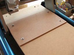
I also needed to raise the sacrificial platform so the tip of the end mill can reach the bottom of the wood. To do that I just cut some more 16″ x 9″ pieces of 1/4″ MDF and stacked them (see the post on fixtures for more information and pictures on what I am talking about).
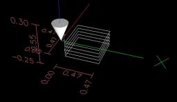
I used CamBam to draw a 0.5″ x 0.5″ square and then created a profile on the inside using my 1.45mm (0.0571″) end mill. CamBam showed me that I would have slightly rounded corners, but that’s ok. I decided to cut the profile in passes, increasing the depth by 0.05″ each time. This results in five passes to get to the bottom of the wood. Tedious, but better than stressing the end mill and Dremel.
I was afraid that the tip of the end mill might bind in the sticky double-sided carpet tape so I held on to the poplar with one hand and kept my finger on the power button with the other hand just in case. I was also afraid that the cube being cut might fly out as it came free.
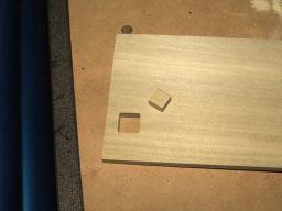
It turned out pretty good. No sticky residue on the end mill and no gouging of the sacrifical platform. The cube in the center held in place during cutting and while I lifted the poplar. It came out when I removed the carpet tape.
The cut is nice and clean with no burrs. I guess the carpet tape is a good method to continue using.
First Steps With CNC
Jun 22nd
Today I took my first steps cutting some scrap pine. I started off with a 2″ diameter circle then measured it. This is an acid test to check the CNC machine for accuracy and squareness. I used a 1.45mm four flute carbide end mill, 10″ per minute speed and cutting to 0.05″ deep.
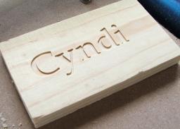
Next I used CamBam to cut my wife’s name. That also went well, however even with the text 1.5″ high I was running into a limitation of the end mill. A small mill would have improved the detail.
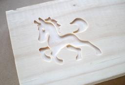
Then I downloaded a DXF file of a horse and tried cutting that. Came out very nicely. The thin strip of wood left between the body and mane is thin enough to see light through it.
Here is a video shows the horse being made.
For all these I used the same end mill and cutting depth as I did for the circle.
Measuring CNC Backlash and Software Compensation
Jun 19th
This article describes how I measured the backlash on my CNC machine and then applied software compensation.
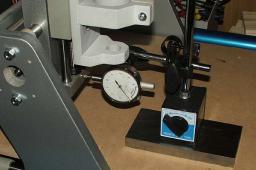
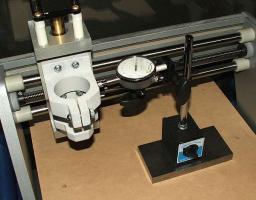
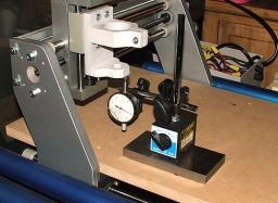
To measure backlash I used a Mitutoyo dial indicator with 0.0001″ markings and a full scale of 0.01″. The dial indicator was attached to an adjustable stand so the plunger could be placed against various surfaces on the machine. The stand had a heavy base to ensure the dial indicator and stand didn’t move when pressure was applied to the plunger.
The picture below shows the set up ready to measure the backlash of the X axis.
Here is the method I used:
- Position the plunger on the dial indicator a short distance from a surface that moves in the direction of the axis being measured. The plunger should be perpendicular to the surface.
- Jog 0.001″ along the axis being measured into the plunger, until the needle moves at least 0.001″.
- Note the value shown on the dial indicator. We’ll call this ‘S’ for start.
- Jog the axis 0.001″ seven times into the plunger. Each jog will cause the needle to move. Be careful not to cause the needle to move to the maximum position.
- Jog the axis 0.001″ seven times away from the plunger. The first one, two or three jogs may not cause the needle to move. This is the slack being taken up and hence the backlash.
- Note the value shown on the dial indicator. We’ll call this ‘F’ for finish.
- Calculate the difference between the finish value and the start value (F -S). This is the amount of backlash.
- Jog the axis away from the plunger
- Repeat two more times then work out the average value.
The next picture shows the position of the dial indicator used to measure the Y axis.
The last picture shows the position of the dial indicator used to measure the Z axis.
For my machine I measured the backlash as (averages):
- X = 0.00538″
- Y = 0.00250″
- Z = 0.00030″
EMC2 provides software compensation for backlash. This isn’t as good as using anti-backlash nuts, but I was curious to see how well it would perform. One thing to keep in mind is that over time wear will cause the backlash to change. To configure EMC2 simply add the backlash values to the axis sections of the INI file. Nice and simple. For example:
[AXIS_0]

...

BACKLASH=0.00538
I then remeasured the backlash and obtained the following values (averages):
- X = 0.00073″
- Y = 0.00010″
- Z = 0.00013″
The Y axis saw the greatest improvement (96%) followed by the X axis (86%) and the Z axis (56%). I think this is pretty good.
Backlash Article
Jun 18th
I just found a nice article on backlash and how anti-backlash nuts work – Backlash in Lead Screws: What It is and What to do About It.
Creating Fixtures For a CNC Machine
Jun 14th
Fixtures are the method used to hold down workpieces, which are the items that will be cut. There are many different ways to do this and the following describes the method I have chosen.
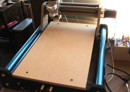
Once my CNC machine was assembled, the surface looked like this:
It is pretty much a piece of wood held down by four bolts. We can’t directly attach the workpiece to this surface however because when we cut all the way through the workpiece we will gouge the surface of the CNC machine. Therefore we need a sacrificial piece of wood in between. This sacrificial wood can be thrown away when it is no longer useful and replaced. In addition to using a method which allows the sacrificial wood to be easily installed and removed, it would be nice to allow different sizes of sacrificial wood.
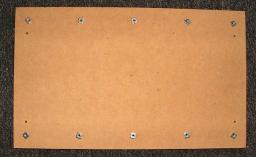
The solution I used for this is a grid of holes which allow bolts to be used. I decided to use a row of five bolt holes down each side of the CNC surface, regularly spaced apart. The four corner holes are 1.5″ in from each edge. The remaining holes are spaced 3 gaps of 6″ and 1 gap of 5.5″ apart along the longest edges.
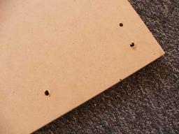
To drill the holes I used a 5/16″ wood spade bit. The next step is to attach 1/4″ – 20 x 5/16″ tee nuts. I achieved this by hammering them in. Attach the tee nuts to the underside of the CNC surface.
After reinstalling the CNC surface I cut a piece of sacrificial wood. I used scrap 1/4″ MDF from Home Depot. A sheet 4ft x 2ft cost me about $5. I cut the MDF down to 16″ x 9″ and drilled 5/16″ holes 1.5″ in from each edge (four holes in total). The MDF was then bolted down to the CNC surface using 1/4″ – 20 x 1″ bolts.
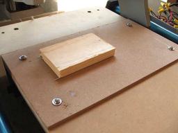
The final step was to use double-sided carpet table to fix the workpiece down onto the sacrificial wood.
