Interesting Tech Projects
Archive for April, 2008
Configuring EMC2 For Three Axis Stepper Motor Control
Apr 29th
There are many ways to configure EMC2, suiting many different uses. But perhaps the most common is control of three stepper motors. This post describes the process I went through to configure EMC2 for my CNC machine, which is a Fireball CNC V90. These steps may not match exactly your needs, but perhaps it will help as a starting point for further exploration.
It assumed that you have managed to get EMC2 installed and have run the latency tests with no overruns. If you are seeing overruns then try the hints on the EMC2 Troubleshooting page.
When you see ‘$’ in this post, it represents the user prompt. Don’t type it, only type the commands that follow. Replace “andy” with your own user name.
First we need to know how many steps per second your PC can generate. To do that we run the kernel latency test:
$ cd /usr/realtime*/testsuite/kern/latency

$ sudo ./run
The test will output a set of numbers. Use the PC to browse the web, play music and check email for a few minutes. However don’t run EMC2. Stop the test and note the largest value in the “ovl max” column. In my case it was 92,191. Values over 100,000 may not give good performance. In general the larger the value the worst CNC performance will be. There are some hints in the EMC2 wiki on how to lower this value.
92,191 means 92.191us (us = microseconds). Between the PC at the stepper motor is a driver chip, such as the SLA7078MR. This chip has some delays that are required for each edge. By reading the datasheet for the driver chip we can find out what this is, and for the SLA7078MR it is 12us. If you don’t know or not sure, I would suggest you pick a value similar to this and err on the side of caution by making the value a bit larger.
So we have 93us (rounded up) + 12us = 105us = 105,000ns (ns = nanoseconds). This is the BASE_PERIOD (more on that in a bit).
Therefore the maximum step rate for my PC is 1 / (105us x 2) = 4,762 steps per second.
It’s possible to tweak the steplen, stepspace, dirsetup and dirhold values to achieve better results than this, but that topic is outside the scope of this post. See the EMC2 documentation for details.
We next need to calculate how many steps are needed to move one inch with 1/4 microstepping. If you wish to use a different microstepping configuration or millimeters then adjust the following calculations accordingly.
My stepper motors require 200 pulses per revolution. This is a very common amount. With 1/4 microstepping it will take 200 x 4 = 800 steps per revolution.
On the X and Y axis of my machine the lead screw has 10 turns per inch but it is has two starts, which makes it 5 turns per inch. This is a pitch of 1 / 5 = 0.2 inches.
Therefore 0.20in / 800 steps per rev = 0.00025in per step.
Therefore 1 / 0.00025in = 4000 steps per inch. 4000 becomes the INPUT_SCALE value for X and Y.
The maximum speed is 4762 steps per second / 4000 = 1.1905in per second = 71.43in per minute. 1.1905 is the MAX_VELOCITY for X and Y.
On the Z axis of my machine the lead screw has 12 turns per inch. This is a pitch of 0.0833in.
Therefore 0.0833in / 800 steps per rev = 0.000104166in per step.
Therefore 1 / 0.000104166in = 9600 steps per inch. 9600 becomes the INPUT_SCALE value for Z.
The maximum speed is 4762 steps per second / 9600 = 0.4960416667in per second = 29.7625in per minute. 0.4960416667 is the MAX_VELOCITY for Z.
We now have all the information needed to complete the configuration of EMC2. First we must copy the example configuration files and then customize them.
$ mkdir /home/andy/emc2/

$ cp /etc/emc2/sample-configs/stepper /home/andy/emc2/

$ sudo chown andy:andy /home/andy/emc2/*
Rename all values to remove “dpkg-new” from the end of the file names. Then:
$ cd /home/andy/emc2

$ mv stepper_inch.ini mymachine_inch.ini

$ nano -w mymachine_inch.ini
Scroll down to the BASE_PERIOD line and set it to the value calculated in nanoseconds. In my case it is 105000.
Scroll down to the trajectory planner and set the MAX_VELOCITY value to the largest MAX_VELOCITY value of all the axis. In my example it is 1.1905.
Scroll down to the section that configures the first axis (X) and set the INPUT_SCALE to the value calculated. In my example it is 4000. Set the MAX_VELOCITY and STEPGEN_MAXVEL to the MAX_VELOCITY value for the axis. In this example it is 1.1905.
Repeat for the Y and then Z axis.
The final step is to edit standard_pinout.hal to match the pinout of your controller board. The important section in the file looks something like:
linksp Xstep => parport.0.pin-03-out

linksp Xdir  => parport.0.pin-02-out

linksp Ystep => parport.0.pin-05-out

linksp Ydir  => parport.0.pin-04-out

linksp Zstep => parport.0.pin-07-out

linksp Zdir  => parport.0.pin-06-out
Simply change the “03”, “02”, etc. values to match the pin numbers used by your board. “Xstep” means the step input for the X axis.
Now run EMC2 using:
$ emc /home/andy/emc2/mymachine_inch.ini
Set the jog rate to the maximum for each axis in turn and jog the axis. It is possible that the axis may stall or lose steps. This is because the value we calculated is a theoretical maximum. However it gives you a starting point to reduce the speed of the axis until it works reliably. To do this lower the jog speed slightly until it works then using the INPUT_SCALE work out a new value for the number of steps per axis. For example, assuming we had to lower the jog speed to 60.000 in per minute on the X axis:
60.000 in per minute / 60 = 1.000 in per second. 1.000 in per second x 4000 steps per inch (INPUT_SCALE) = 4000 steps per second
Now a new value for BASE_PERIOD can be calculated:
1 / 4000 steps per inch / 2 = 125,000ns
Edit mymachine_inch.ini and set the new BASE_PERIOD value. Note that this will lower the speed of all axis. Recalculate the MAX_VELOCITY value for all axis and update the configuration file with the new values. Then retest.
I found that on my PC it can operate at the theoretical maximum speed without problems. I hope this helps you configure EMC2 for your machine.
First Steps With EMC2 and AXIS
Apr 28th
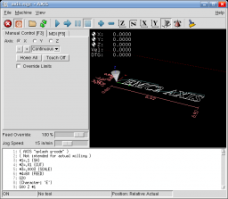
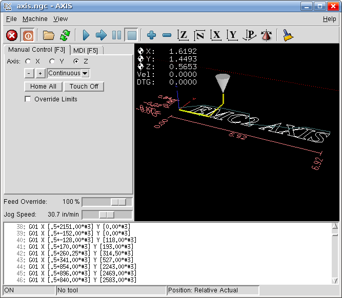
This post describes the first steps after running EMC2 with the AXIS interface for the first time. To start choose AXIS -> Sim from the menu after starting EMC2.
Starting the attached CNC machine (in this case a simulation) requires two steps. First the emergency stop (e-stop) must be turned off. Then power must be turned on.
To turn off the e-stop click on the toolbar button that looks like a red circle with an “X” in it.
To turn on the machine click on the toolbar power button (to the right of the e-stop button).
At this point most of the user interface should now be enabled. Until you have a real e-stop button connected to your machine, you can click on the toolbar E-stop button at any time to stop the machine.
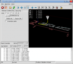
Drag the “Jog Speed” slider to something like 30 in/min. Now to jog the axis. Make sure the “Manual” tab is selected.
- Select one of the axis X, Y or Z
- Choose “Continuous” from the drop down list
- Click on the “+” and “-” buttons to jog. Watch the cone move in the display
- Now try a different axis
The display also shows the current X, Y and Z position in inches of the tip of the cone, which represents the tool (drill bit).
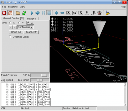
Now try clicking on the execution toolbar button, represented by a blue triangle. EMC2 will execute the loaded g-code file, which outlines some text. Watch the cone move as the code is executed. There are additional toolbar buttons to pause, step through and stop execution.
To zoom in on the display move the mouse over the display and use the scroll wheel on your mouse. Alternatively press the right mouse button and drag.
To pan the display move the mouse over the display, press the left mouse button and drag.
To rotate the display move the mouse over the display, press the scroll wheel and drag.
There are also toolbar buttons to control this operation. In addition there is a toolbar button representing a broom. Clicking on this will clear the lines showing the path that the tool has made.
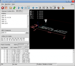
Next click on the “MDI” tab to access the command line interface. In the MDI Command box enter:
G00 X0 Y0 Z0
Watch the cone move back to the origin in the display. Now try the following and watch the cone move:
G00 X1

G00 Y2

G00 Z0.5
At this point the cone should be at 1, 2, 0.5. Any number of axis can be moved at once, and the number after the axis name is the absolute position. For example:
G00 X2 Y2.5

G00 X0 Z0.1

G00 X0 Y0 Z0
G00 means move the tool as quickly as possible. This is only used when not cutting, as it is typically too fast to move the bit through a material.
Note that all the numbers used in this tutorial are in inches, however it is easily possible to configure EMC2 and AXIS to use millimeters. In which case G00 X1 would move along the X axis one millimeter.
CNC Machine Cabinet
Apr 7th
I have started designing a cabinet to hold my CNC machine. This will allow viewing of the machine as it works and keep the mess to itself. It will also have a location for the electronics to keep everything self contained. Some anticipated features:
- Electronics storage with location for cooling fan
- Windows on two sides for observation
- Doors on two sides for easy access
- CNC machine sits on a sliding shelf for easy installation and removal
- ESTOP and power switches on front of machine
- Printer port connector (DB25) on back
- Minimises amount of chips and debris reaching electronics
- Power outlet for rotary tool
Once it is completed pictures will be posted.
Fireball CNC V90 Limits and Speed
Apr 7th
Yesterday I performed some testing on my Fireball CNC V90. I started off with each axis pretty much centered, to reduce the risk I crash the machine into it’s hard limits (the physical limits of each axis).
Using the full stepping inches configuration I tried:
G00 X1
to move the X axis (the longest axis) one inch. The motor accelerated and then stalled. This results in a nasty whirring/vibrating sound and no movement. A bit like crunching a gear in a manual transmission car. I found the same for the other two axis.
Next I tried moving the axis at slower speeds by specifying the inches per minute (IPM):
G01 F30 X1

G01 F50 X0

G01 F60 X1
etc. I found that I could achieve the following speeds before the motors stalled:
- X: 148 IPM
- Y: 80 IPM
- Z: 33 IPM
Fireball CNC confirmed that Y will operate slower due to the different forces on the rails.
The next step is to try 1/4 stepping. This will result in a lower speed, but will increase the torque, so it should be possible to get a little bit closer to the theoretical maximum speed.
I also measured the following amount of travel for each axis:
- X: 17.85 inches
- Y: 11.7 inches
- Z: 2.75 inches
Since I received my machine Fireball CNC has increased the Z axis travel slightly.
