Interesting Tech Projects
Archive for October, 2007
Maximizing The Work Area
Oct 11th
For a given frame size, the machine will be limited in the size of object that it can work on. So what size frame is needed? First we must look at the design of the machine and see where the limits are.
To maximize the X size, the nut that goes on the X leadscrew should be as near to the center of the X platform as possible. This will allow the center of the platform to get as close to each side as possible. As the center will be on the inside, the platform should remain stable. Also the platform should be able to pass over the top of the X motor. This would allow an object nearly as wide as the machine to be worked on. The movement in the X direction will be limited by the distance between the “legs” of the machine. Also the bit must be located halfway between the sides of the machine.
To maximize the Y size, the bit should be positioned so that it is half way between the back and the front of the machine. The nut for the Y leadscrew can be anywhere from the back of the platform to the center, because travel is limited towards the back by the upright that is holding the rotary tool. Also the platform should be able to pass over the top of the Y motor. If the center of the Y platform moves beyond the front most X rail, then there is a danger that the platform could tip over, therefore the distance between the X rails limits the range of motion of the Y platform. This would allow an object with a depth of about half the depth of the machine to be worked on.
To maximize the Z size the upright holding the Z platform should be tall enough to accomodate the largest object, but also allow the bit to get down to the Y platform for small objects. This can be achieved by using rails of a suitable length to allow for the range of motion. If stability is needed when the tool is at the highest point, weight could be added to the front end of the “legs” of the machine.
Conclusions:
So it seems to me that it is important for the rotary tool to be centered in the X and Y directions, which is a feature not present in the McWire original design. Also for a desired object of size A x B, the machine should be built so that is it A wide and B x 2 deep (measured on the inside of the pipes used to construct the base). The X rails should extend half the X platform width on each side past the pipes. The Y rails should extend half the Y platform depth beyond the front most X rail. The X platform width should be at least half the distance between the “leg” pipes. The Y platform depth should be a bit more than the width of the X rails.
The stepper control board I have chosen has support for limit switches which could be employed to stop the platforms from moving too far and either coming off the rails or causing damage to the machine.

Rotary Tool Purchased
Oct 11th
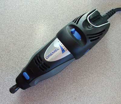
I have purchased the rotary tool I will use for the CNC machine. I picked a which features variable speed. Variable speed is useful for machining different materials, for example higher speeds for metal and lower speeds for plastic. This is a pretty good quality tool with no play where the bits attach and has a five year warranty. It will be removable from the machine to use for other things as well.
I needed to purchase this early so I can build a custom frame for it to fit snugly into. It’s important that is isn’t possible for the tool to move during operation of the machine otherwise the accuracy goes out of the window.
Interface and Motors Picked
Oct 9th
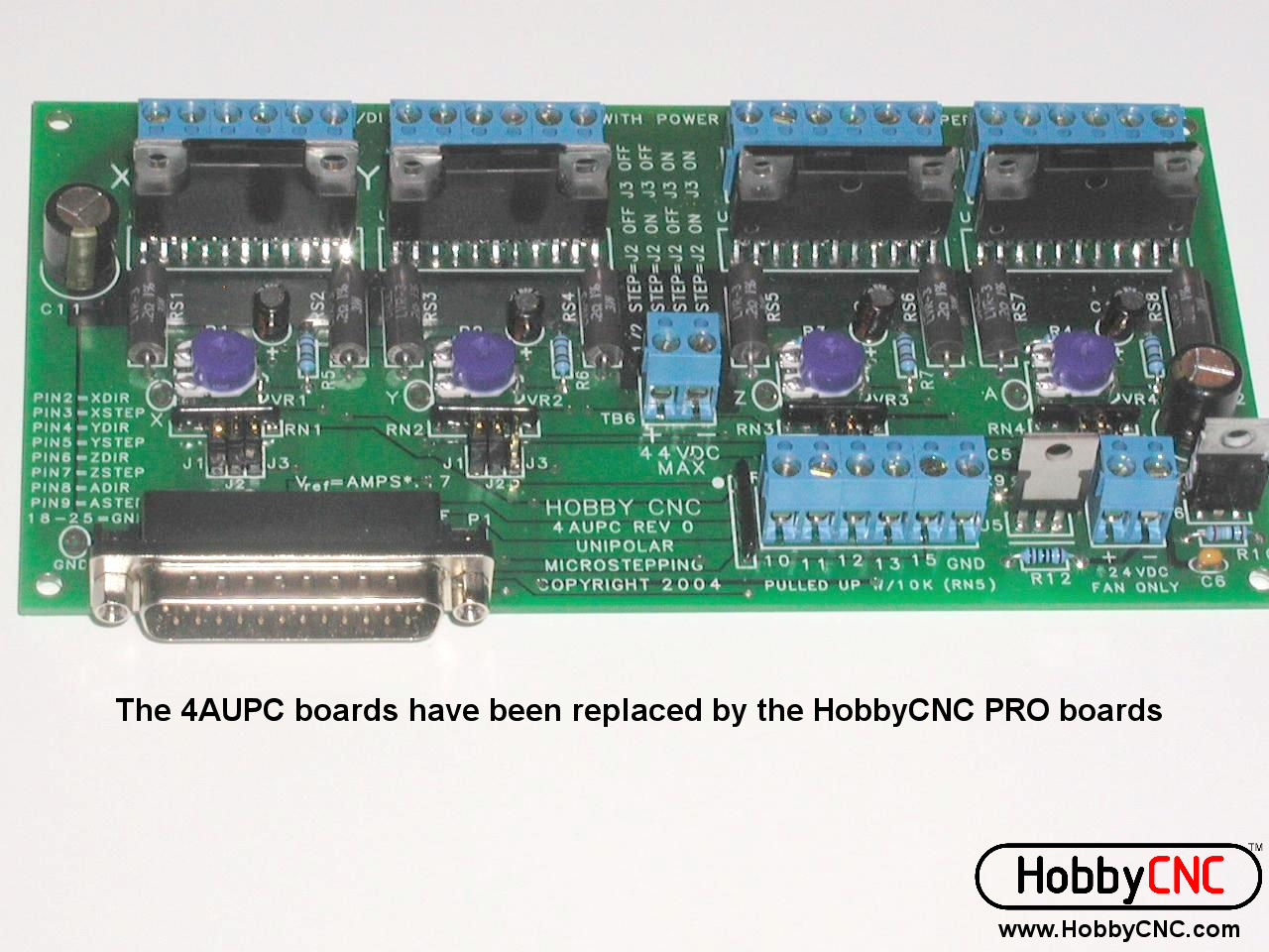
I finally decided to go with Hobby CNC’s 4AUPC Chopper Driver Board Kit With 23-305-DS8 6V 2A Stepper COMBO. This is a kit that contains:
- Combined interface board and drivers for 4 axis
- Interface features choppers and microstepping down to 1/16
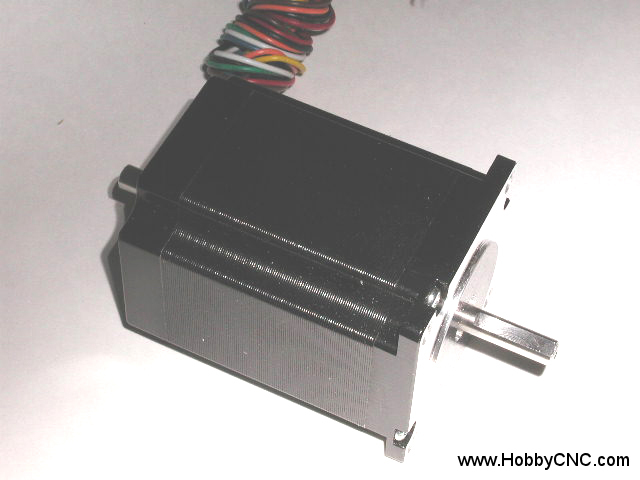
- Three 305 oz-in unipolar motors with 1.8 degrees per step
Why did I choose this? When I looked more closely at the PICStep design it required two LMD18245T drivers per axis. Digi-key sells these for about $13 each. That adds up to 6 x $13 = $78. Plus each driver has a $3 PIC microcontroller, so the PICStep drivers are at least $87. On top of that an interface between the drivers and the PC is required plus some minor bits and pieces for the drivers. The interface is pretty simple and would cost maybe $15. So the total is around $105 plus shipping for the parts. It may be possible to find a slightly cheaper microstepping driver, but it would likely shave off just a few dollars per driver. If anyone has any specific drivers and totals please post a comment.
Next issue was the motors. I wanted motors that other people could purchase to get the same results. Reproducability is a key aim of this project. That means no surplus or used motors where the exact specification is not known. So I was looking at new motors. Also the motors have to have enough torque to drive the drill bit into the material and move the platform around, pushing the material into the drill bit. No exact figures are available but I get the impression that at least 120 oz-in is needed to avoid having the motors stall, and in general the more torque the better. The cheapest motors I could find with a suitable specification were item 11A from Keling, Inc. at $30 a piece. The total would be $90 plus shipping.
Now compare these figures to the Hobby CNC combo. I get all the electronics and 305 oz-in motors, which are more than twice as powerful as the ones from Keling, for $160 plus shipping, which is less than I would be paying for the PICStep approach. Plus I can be sure that the motors will match the electronics and Hobby CNC provides technical support. Also I get 1/16 microstepping instead of 1/8 with the PICStep.
Now I suppose it would be possible to redesign the PICStep drivers to use cheaper motor driver ICs, such as the ones used by the Hobby CNC board, but I don’t have time to do that right now. I want to get my CNC machine up running and then maybe redesign the electronics later.

(pictures from Hobby CNC)
Torque Conversion Table
Oct 8th
Some stepper motors are quoted in g-cm and some are in oz-in. Here is a handy table to convert between the different units of torque so motors can be compared:Torque Conversion.
Stepper Motor Drivers and Interface
Oct 8th
We have to connect the stepper motors (three, one each for X, Y and Z axis) to a PC. This is achieved with an interface board and drivers. The interface board typically connects to the PC’s printer port and then connects to the drivers. We need one driver for each stepper motor.
When looking at what is available there are a lot of choices. Some come in kits, some are open source and some are just pieces of designs. I decided not to use the design used by Tom McWire for a couple of reasons:
- Using a microcontroller on the board reduces some of the real time requirements on the PC. The microcontroller can perform some local processing instead of having to rely on the PC to provide all the signals
- Supporting microstepping allows for finer control over the motor. Essentially microstepping further divides the steps provided by the motor. This can give a higher precision and smoother operation
In addition I have the following requirements for the hardware:
- Able to be configured to support specific PC applications
- Simple design
- Able to drive NEMA-23 stepper motors
- Uses a common microcontroller
- Preferably open source
I found the following website full of designs: PMinMO Electronics, including a Parallel Port Reference. Of these designs only a few support microstepping. Of those I am currently considering using the PICStep. Further research is required however to make sure it will be possible to interface to the PC applications I am interested in using.
Low Cost CNC Milling Machine
Oct 4th
The primary purpose of this blog is to document specific technical projects that I will have a go at. First up is an attempt at building a low cost but precise CNC milling machine. I will follow the design by Tom McWire shown here: Easy to Build Desk Top 3 Axis CNC Milling Machine.
So now you are wondering, why bother if how to build this machine has been described on the internet already? Because my aim is reproduceability and accuracy. The problem right now is that if two seperate people decide to each build a machine from the instructions, they will end up with slightly different machines that perform differently. For example the dimensions of the machine and which stepper motors used are missing. I want a set of instructions that people can follow to yield predictable results.
Also missing is a description of the kind of accuracy that can be expected. At this point I am not sure if this machine can generate an accuracy good enough for my needs. Hopefully it will. If I can figure out what design decisions to make to achieve the accuracy I need, and document them, then other people will know up front exactly what they need to do to also get the same accuracy. My aim is to be able to engrave commemorative coins. These coins have a small area where a name can be placed, and this will require precision.
I hope to also make some minor improvements here and there, and it might involve a few iterations before the machine works well enough. One of Tom McWire’s aims was to build it in less than $200. I also have the same aim, but if a situation arises where I can spend a few dollars more to increase precision then I will do it. For example I won’t be getting old motors from printers because they are all different and someone else cannot then come along and follow my instructions to get the same machine. Instead the specifications of the motors I use must be known.
(picture from Easy to Build Desk Top 3 Axis CNC Milling Machine)
